Ford Parts Wiki | GM Parts Wiki
Home | Search | Browse
|
Technical Service Manual January 1975 |
|
Prev
 Next
Next
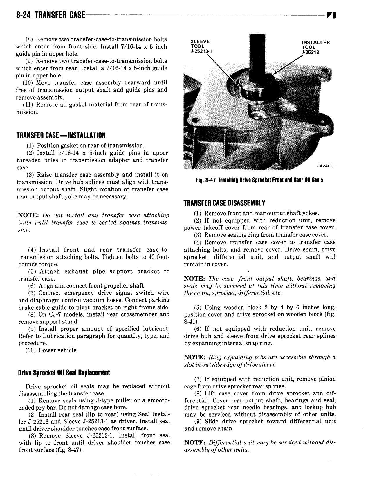
8 24 TRANSFER IIASE rn 8 Remove two transfer case to transmission bolts SLEEVE INSTALLER which enter from front side Install 7 16 14 x 5 inch VOOL TDOL guide pin in upper hole Mszim 25213 9 Remove two transfer case to transmission bolts V which enter from rear Install a 7 16 14 x 5 inch guide V V i g o i 1 pin in upperhole 9 10 Move transfer case assembly rearward until Inj R 3 free of transmission output shaft and guide pins and r i remove assembly ji l or V e 11 Remove all gasket material from rear of trans 1Y j f miasiaii ifs egg musrni use inmtunuu 2 3 1 Position gasket on rear of transmission im f i 2 Install 7 16 14 x 5 inch guide pins in upper ry i i threaded holes in transmission adapter and transfer W F i case Q3 i 4 45 6 Jazsoi 3 Raise transfer case assembly and install it on transmission Drive hub splines must align with trans Fl 841 l l Imwsiimlim Fr M01 hm mission output shaft Slight rotation of transfer case rear output shaft yoke may be necessary TIIIIISFER CASE DISASSEMBLY Nom ot tat tttttan any transfer taaa attaching 1 R m v fr d r h f y9k bolts until transfer case is seated against transmis 2l If mt equipped wlth reductmn mt r m v si power takeoff cover from rear of transfer case cover 3 Remove sealing ring from transfer case cover 4 Remove transfer case cover to transfer case 4 Install front and rear transfer case to attaching bolts and remove cover Drive chain drive transmission attaching bolts Tighten bolts to 40 foot sprocket differential unit and output shaft will pounds torque remain in cover 5 Attach exhaust pipe support bracket to transfer case NOTE The cose front output shaft bearings and 6 Align and connect front propeller shaft seals may be serviced at this time without removing 7 Connect emergency drive signal switch wire thechain sprocket differential etc and diaphragm control vacuum hoses Connect parking brake cable guide to pivot bracket on right frame side 5 Using wooden block 2 by 4 by 6 inches long 8 On CJ 7 models install rear crossmember and position cover and drive sprocket on wooden block fig remove support stand 8 41 9 Install proper amount of specified lubricant 6 If not equipped with reduction unit remove Refer to Lubrication paragraph for quantity type and drive hub and sleeve from drive sprocket rear splines procedure by expanding internal snap ring 10 Lower vehicle NOTE Ring expanding tabs are accessibk through a slot in outside edge of drive sleeve Driva Spronlm UII Sul Rsplacsmni 7 If equipped with reduction unit remove pinion Drive sprocket oil seals may be replaced without cage from drive sprocket rear splines disassemhling thetransfer case 8 Lift case cover from drive sprocket and dif 1 Remove seals using J type puller or s smooth ferential Cover rear output shaft bearings and seal ended pry bar Do not damage case bore drive sprocket rear needle bearings and lockup hub 2 Install rear seal lip to rear using Seal Instal may be serviced without disassembly of other units ler I 25213 and Sleeve J 25213 1 as driver Install seal 9 Slide drive sprocket toward differential unit until driver shoulder touches case front surface and remove chain 3 Remove Sleeve J 25213 1 Install front seal with lip to front until driver shoulder touches case NOTE Differential unit may be serviced without dis front surface fig 8 47 assembly ofother units