Ford Parts Wiki | GM Parts Wiki
Home | Search | Browse
|
Technical Service Manual January 1975 |
|
Prev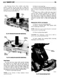
 Next
Next
812300
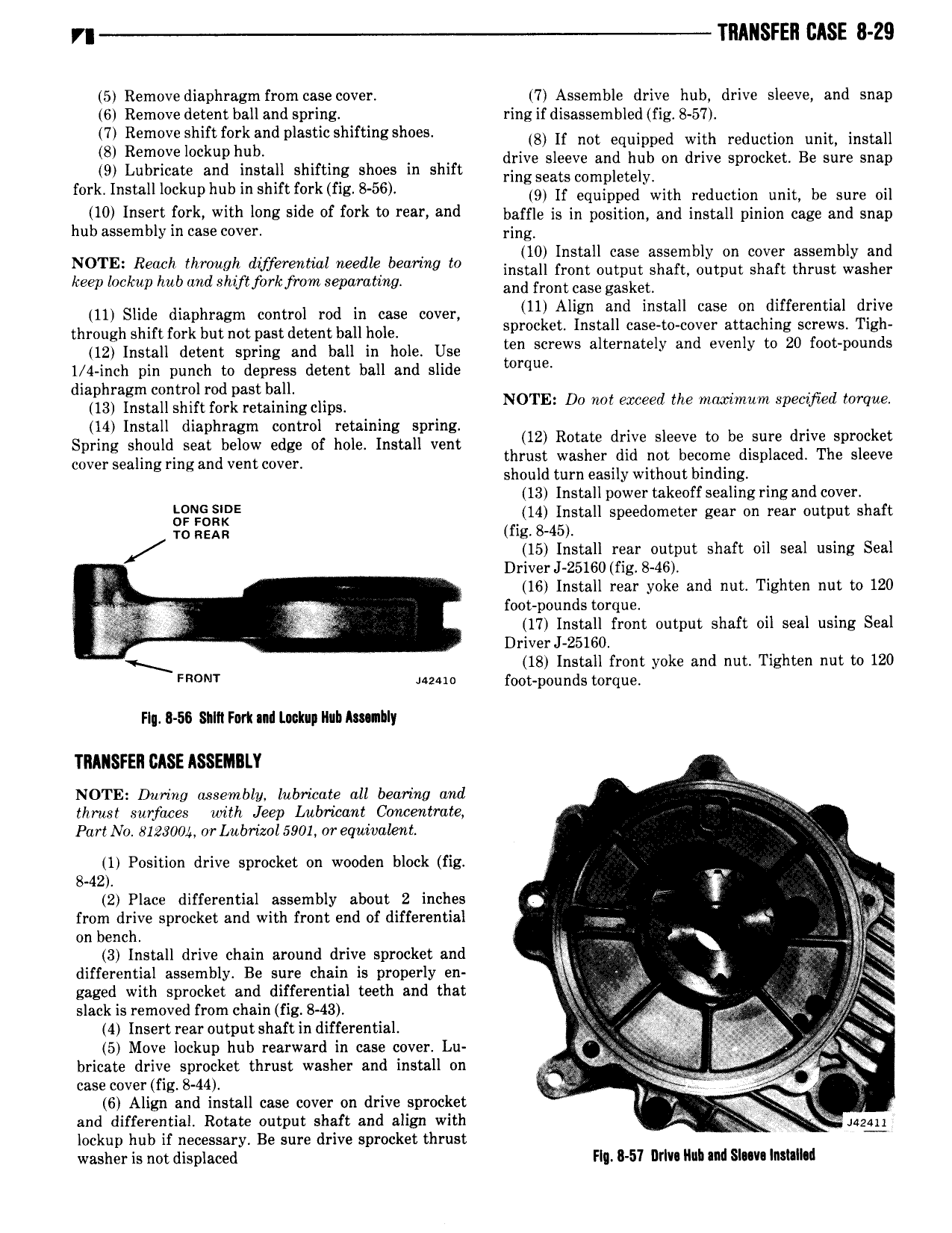
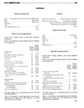
TRANSFER EASE 8 29 5 Remove diaphragm from case cover 7 Assemble drive hub drive sleeve and snap 6 Remove detent ball and spring ring if disassembled fig 8 57 Q games h jk j d a io ii iiiii equipped Wiiii ieiiiiiiioii iiiii iiimii emqve Oc up u drive sleeve and hub on drive sprocket Be sure snap 9 Lubricate and install shifting shoes in shift ringseats wmpletelv f rk InSta H kup h bm shm fm k flg 8 56 9 If equipped with reduction unit be sure oil 10 I S i f0 k with l E 1d of Drk to Fei and baffle is in position and install pinion cage and snap hub assembly in case cover ring NOTE R eh Waugh wf l eee mic M i S 3i l L i2i1 2i i l 3S i i 2 i i i E 2 Jl I Z keep lookup hub aud shift fork from separating and from case gaskx 11 Slide diaphragm control rod in case cover ul Alggn Td install WSE hcliueremlal grilae through shift fork butnotpast detentball hole Spmc EL ns Si t c 2l er ataac m 9WS lgd 12 Install detent spring and ball in hole Use mn Screws atemmey an eveny to t p u B 1 4 inch pin punch to depress detent ball and slide torque l od dIEgg 85 t T ftrf0r i l ng clips NOTE Do not exceed the maximum speczyied torque 14 Install diaphragm control retaining spring Spring should seat below edge of hole Install vent h 12l Rotaxe dg Bleege t bifsufe d w hSpr k t cover sealing ringand ventcover ms was er 1 fw Ecllmg Sp ace 9 seeve should turn easily without binding 13 Install power takeoff sealing ring and cover TE 14 Install speedometer gear on rear output shaft 1 0 REAR fig 8 45 15 Install rear output shaft oil seal using Seal s Driver J 25160 fig 8 46 g EV 16 Install rear yoke and nut Tighten nut to 120 re 2 V foot pounds torque 17 Install front output shaft oil seal using Seal i V DriverJ 25160 A g 18 Install front yoke and nut Tighten nut to 120 FRONT Mum foot pounds torque Flu B 56 SIII1 Fork and Lookup Rub Ammhly TRAIISFER CASE ASSEIAIILY NOTE During assembly lubricate all bearing and L thrust surfaces with Jeep lxubrricaut Concentrate Part N0 812300 or Lubrizol5901 or equivalent 1 Position drive sprocket on wooden block fig i V QV 842 V T gw 2 Place differential assembly about 2 inches Q Q from drive sprocket and with front end of differential r uw on bench N r 3 Install drive chain around drive sprocket and b differential assembly Be sure chain is properly en f s gaged with sprocket and differential teeth and that Qt V Q 5 fw Cs slack is removed from chain fig S 43 i i Q 4 lnsertrearoutputshaftin differential FV Ufgc a 5 5 Move lockup hub rearward in case cover Lu Y i oy gf bbw bricate drive sprocket thrust washer and install on V 7 ag y V case cover fig 8 44 6 Align and install case cover on drive sprocket v R i IV and differential Rotate output shaft and align with 7 4424 lockup hub if necessary Be sure drive sprocket thrust washer is not displaced Fly 8 51 lIrlv Huh and Sum Insulkd