Ford Parts Wiki | GM Parts Wiki
Home | Search | Browse
|
Technical Service Manual January 1975 |
|
Prev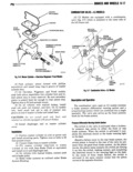
 Next
Next
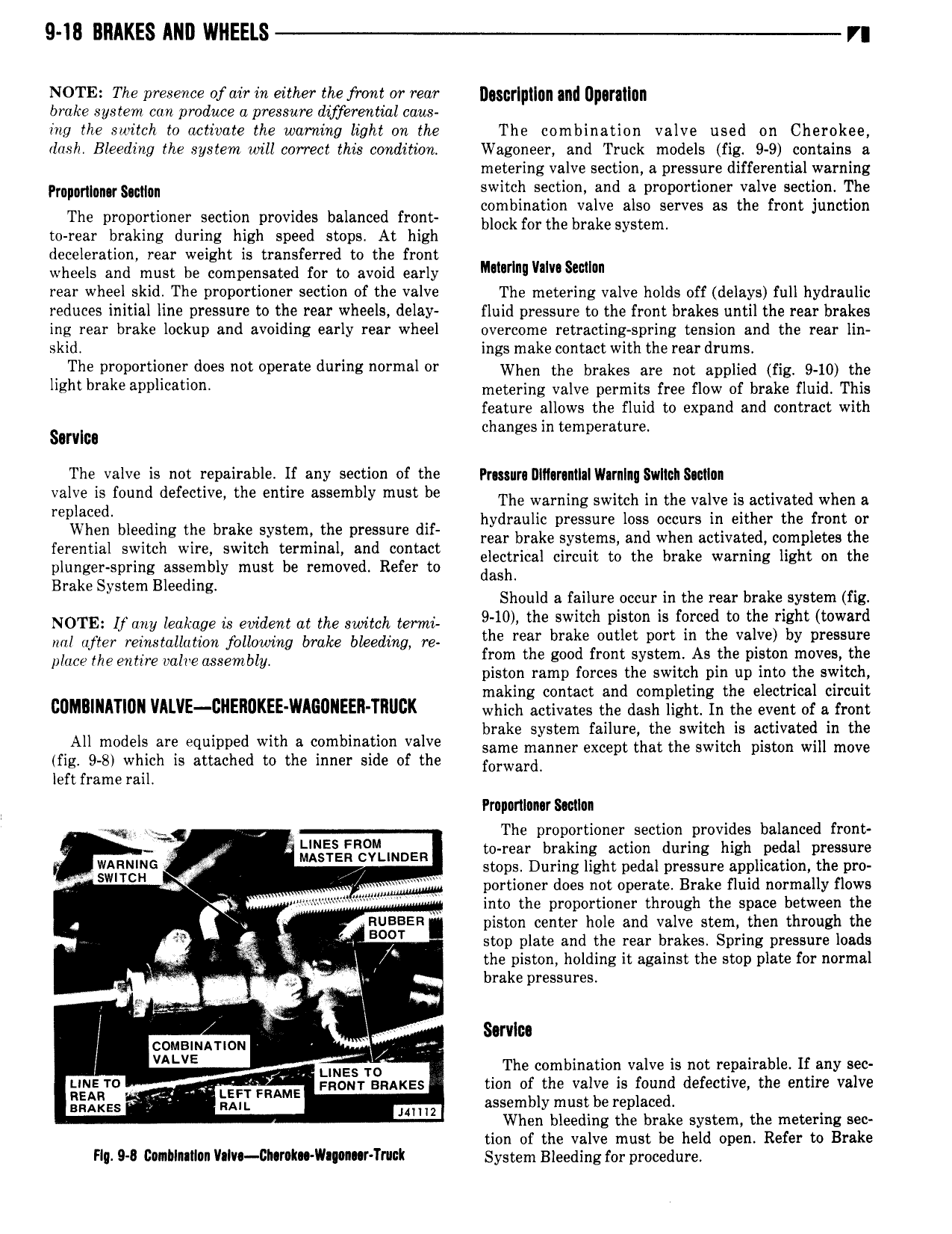
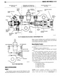
9 18 BRAKES AND WHEELS V NOTE The presence of air in either the fmrit or rear Dmrlpflgn and Dpgnllgn brake system can produce a pressure differential caus ing the switch to activate the wanting light ori the The combination valve used on Cherokee dash Bleeding the system will correct this ccmditum Wagoneer and Truck models fig 9 9 contains a metering valve section a pressure differential warning pmpammu smm switlejh section end e proportioner ttkalvie seetlon Qljhe t v a on unc ion The proportioner section provides balanced front ggklgi iz brzlzssb ss grserves S Q r J to rear braking during high speed stops At high A deceleration rear weight is transferred to the front wheels and must be compensated for to avoid early lmmnl ml s rear wheel skid The proportioner section of the valve The metering valve holds off delays full hydraulic reduces initial line pressure to the rear wheels delay fluid pressure to the front brakes until the rear brakes ing rear brake lockup and avoiding early rear wheel overcome retracting spring tension and the rear lin skid ings make contact with the rear drumst 4 The P P l i d not 01 9 dun normal l When the brakes are not applied fig 9 10 the Mzhtbrake v s metering valve permits free How of brake fluid runs feature allows the fluid to expand and contract with hanges in temperature Sorvlcn The valve is not repairable If any section of the Prusurl llIl r nlIIIWlrnlI Svlllcll Sltlllll Val jif d V me mrs y must be ne warning renter inthe valve re activated when r rep hydraulic pressure loss occurs in either the front or f he bl td j le brake ymm pwgm gy smite systems ere when eetmtee completes tre Hamm Slime Mm Swim mrmma an con C electrical circuit to the brake warning light on the plunger spring assembly must be removed Refer to dash B k s t Bl d ra E ls em ee mg Should a failure occur in the rear brake system fig NOTE U my leakage L9 evident at me Swieeh term 9 10 the switch piston is forceg to the right toward rel rlfeer reiuestallutiou jbllowiug brake bleeding re h b k l Pm il l Y place me entire whe assemble from the good front system As e pieton moves e piston ramp forces the switch pin up into the switch making contact and completing the electrical circuit UDMBINITIUII VIl VE CllERUKEE WIGUNEER TIUcK which activates the dash light In the event of a front brake system failure the switch is activated in the All m s are d WM 9 mb valve same manner except tnet the Seiten meter will move fig 9 Sr which is attached to the inner side of the f0rwe1 d left frame rail Prupnnlnnar Smlun eq he e E The proportioner section provides balanced front NE F to rear braking action during high pedal pressure Masrsn cvuuoen WARNING gf stops Dui ing light pedal pressure application the pro V SWITCH 4 We I purticner does not operate Brake fluid normally laws ereee t into the proporthmer through the space between the V RUBBER piston center hole and valve stem then through the g i V BO T stop plate and the rear brakes Spring pressure loads V Ye Vl V the piston holding it against the stop plate for normal V e brake pressures r i l Sorvlos l cousimmou I wg l VALVE V LIN S The combination valve is not repairable If any sec tm ro Fnom snakes tion of the valve is found defective the entire valve REAR f A LEFT FRAME bl m the re laced snaxzs RAIL Mm GSSBFH Y 1 P When bleeding the brake system the metering sec tion of the valve must be held open Refer to Brake Fly Q Canblnllon Vnlv I2I rok Wa o r Trlck System Bleeding for procedure