Ford Parts Wiki | GM Parts Wiki
Home | Search | Browse
|
Technical Service Manual January 1975 |
|
Prev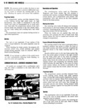
 Next
Next
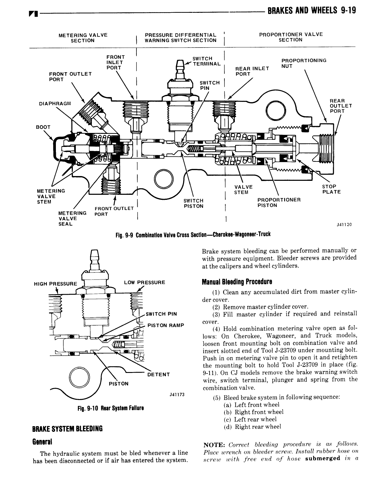
VI RRAKES ANI WHEELS 9 19 Mersnmrs vALvE enzssunz oisssnznrnst pnoponriouen vA ve Szcnow wmumc swnrcu sacmm I sermon unter I QI m m I Pnoponrionnne TTONT OUTLET l I M nom I E PON swrrcri I 1 I nmvunnom gg i mann l zg gg ouuar k 1 gi pom I RIIF B T A 7 r Q la m A w r ELL I g T re QM TT T gg A I w i L JI I I vstvz srow IKEEEING i I srzm A rE srzn f I swnrci 1 nnononnouzn mom 0uTLE r P T N sT N nzrsnmo mm I VALVE I SEAL J4 2B Flu 9 D Conhlnnllnn VaIv Gm SaclI n Bhamka Wagonnr Truck Brake system bleeding can be performed manually or with pressure equipment Bleeder screws are provided at the calipers and wheel cylinders E Hm EEESSURE Q ww ensssuns Manual Iludlnq Prumilurn gj 1 Clean any accumulated dirt from master cylin I der cover g F 2 Remove master cylinder cover F I SWHCH Pm 3 Fill master cylinder if required and reinstall li 7 Piston RAMP v r 4 Hold combination metering valve open as fol 4 v 14 i M lows On Cherokee Wagoneer and Truck models loosen front mounting bolt on combination valve and 4 vg insert slotted end of Tool J 23709 under mounting bolt Push in on metering valve pin to open it and retighten 1 the mounting bolt to hold Tool J 23709 in place fig DETENT 9 11 On CJ models remove the brake warning switch PISTON wire switch terminal plunger and spring from the combination valve mln 5 Bleed brake system in following sequence nl a no n rsym nni m l f f Wh b Right front wheel c Left rear wheel BRAKE SYSTEM RLEEDIIIG td Right rear wheel mm NOTE Correct bleeding procedure is as jbllows The hydraulic system must be bled whenever a line Place wrench on bleeder screw Install rubber hose on has been disconnected or if air has entered the systeml screw with free end of hose submerged ir az