Ford Parts Wiki | GM Parts Wiki
Home | Search | Browse
|
Technical Service Manual January 1975 |
|
Prev
 Next
Next
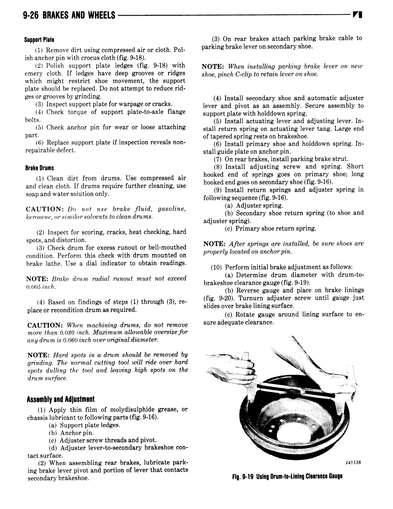
9 26 BRAKES ANI WHEELS YI Support Plata 3 On rear brakes attach parking brake cable to 1 Remove dirt using compressed air or cloth Pol parking brake lever n Secondary shoe ish anchor pin with crocus cloth fig 9 18 2 P ll h SUPDOTY Plate ledees HE 948 with NOTE When installing parking brake lever on new emery cloth If ledges have deep grooves or ridges Shim pinch gcgip to Tetaingevw on 8 we which might restrict shoe movement the support plate should be replaced Do not attempt to reduce rid ees r grmves bygrinding 4 Install secondary shoe and automatic adjuster 3 Inspect Support plate fw Warpage OI r kS lever and pivot as an assembly Secure assembly to b KM Check torque of support plate to axle flange supportplate with holddown Spring o s 5 Install actuating lever and adjusting lever In 0l Check m l l Y Pm fl Wea OY 10059 attaching stall return spring on actuating lever tang Large end pam of tapered spring rests on brakeshoe ii Replace support plate if inspection reveals non 6 Install primary shoe and holddown Spring Im repamble defecb stall guide plate on anchor pin 7 On rear brakes install parking brake strut Iraku llrums 8 Install adjusting screw and spring Short to cen an from drums Use compressed air msg my Of dm g gr 9 me and clean cloth lf drums require further cleaning use g n gges on sewn frys mi I5 Soap and Wamrsolution only nsta return springs an a juster spring in following sequence fig 9 16 CAUTION Do not use brake fluid gasoline 8 d Iust spring h kerosene nrximllursolcehts to clean dmmg adjusteilzl r gndafy S 0e return spring to s oe and prin 2 Inspect for scoring cracks heat checking hard cl Pnmuy shoe rem gpm lg spots and distortion t3 Check drum for excess mmol or bell mouthed N0TEl fler swings litre installed be sure shoes are condition Perform this check with drum mounted on pmper V cate on imc 07 pm k l h l d d bm 6 at 9 Use 3 dla m lcatmi to Dbtam ma mg 10 Perform initial brake adjustment as follows NOTE site lm radial mma me not evceed D dw diameter WM 0 005 inch brakeshoe clearance gauge fig 9 19 A b Reverse gauge and place on brake linings 4 Based On findings of Steps 1 through 3 m fig 9 20 Turnurn adjuster screw until gauge just place or recondition drum as required Shdes Over brake hm surface c Rotate gauge around lining surface to en CAUTIONz When machining drums do not remove Sure adequate clearance more than 0 080 inch Maximum allowabk oversrlze forr any drum is 0 060 inch over original diameter NOTE Hard spots in a drum shnyuld be renwoed by r rj r grinding The normal cutting tool will ride over hard spots dulling the tool and leaving high spots on the 4 g drum surface 3 iu Amnhly and Adluslmm g 1 Apply thin film of molydisulphide grease or F chassis lubricant to following parts fig 9 16 rx V a Support plate ledges L V Q b Anchor pin s z c Adjusterscrew threads and pivot A i d Adjuster lever to secondary brakeshoe con tact surface 2 When assembling rear brakes lubricate park mus ing brake lever pivot and portion of lever that contacts secondary brakeshoe Hq 949 Using llnnn l Llnlng Clnrnnn Gam