Ford Parts Wiki | GM Parts Wiki
Home | Search | Browse
|
Technical Service Manual January 1975 |
|
Prev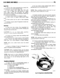
 Next
Next
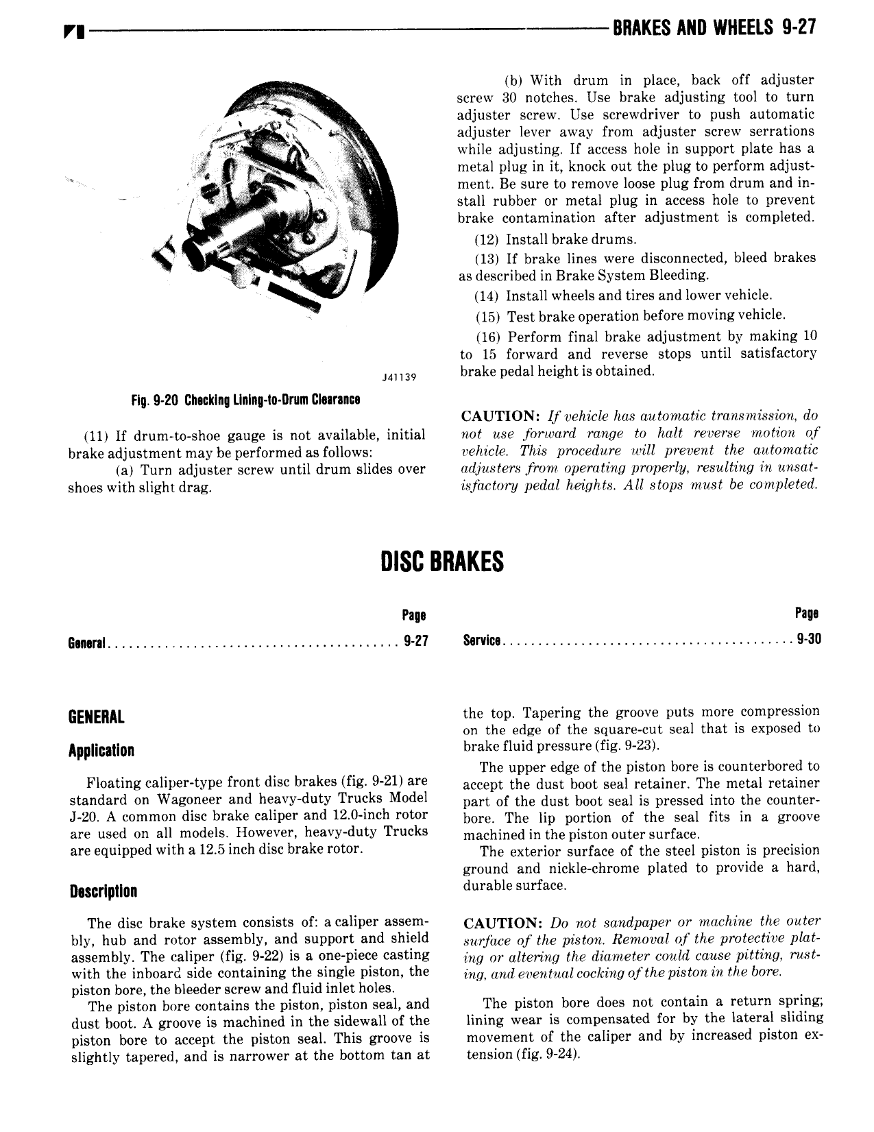
VI BIIAKES ANI WHEELS 9 27 b With drum in place back off adjuster screw 30 notches Use brake adjusting tool to turn adjuster screw Use screwdriver to push automatic J adjuster lever away from adjuster screw serrations er f while adjusting If access hole in support plate has a t 7 metal plug in it knock out the plug to perform adjust R Q 1 ment Be sure to remove loose plug from drum and in 2 r 4 fg stall rubber or metal plug in access hole to prevent V brake contamination after adjustment is completed i y 12 Installbrake drums Q i 13 lf brake lines were disconnected bleed brakes g J as described in Brake System Bleeding N 14 install wheels and tires and lower vehicle 15 Test brake operation before moving vehicle 16 Perform final brake adjustment by making 10 to 15 forward and reverse stops until satisfactory brake pedal height is obtained mm Flg 9 Z0 Clmklng Llnlng to llnim I rm CAUTION If vehicle has automatic trarismission do 11 lf drum to shoe gauge is not available initial not use forward range to halt reverse motion of brake adjustment may be performed as follows vehicle This procedure will prevent the automatic a Turn adjuster screw until drum slides over ruljusters from operating properly resulting in unsat shoes with slighi drag isjiictory pedal heights All stops must be completed Pap Page Gmral 9 Z7 Smloa 9 30 GENERAL the top Tapering the groove puts more compression on the edge of the square cut seal that is exposed to Ip IIi0Ili Il brake fluid pressure fig 9 23 The upper edge of the piston bore is counterbored to Flormrrg c l l r rYp9 from disc brakes if g 921 are accept the dust boot seal retainer The metal retainer t l ld l d 0ll Wcecnccr and ll VY d tY Tl YkS Model part of the dust boot seal is pressed into the counter J 20 A common disc brake caliper and 12 0 mch rotor here The hn nhrtien of the seal fits in n groove are used on ali models 4 However heavy duty Trucks niaehined in the piston enter Snrr nee al Bllulplled Wltha 12 5lll l disc hrchc r t r The exterior surface of the steel piston is precision ground and nickle chrome plated to provide a hard m p n durable surface Thc disc hrekc cycccm c i cfr cccllrcr mem CAUTION Do not Sumipaper or machine me moe hly huh and r y cscchilvlin and i vcr wl Shlcld mjzm ofthe pam aemumiz ofthe protective pmt assemblr The caliper fig 9 22 is a cnc wccc cestlhz my m anermg me diameter mia muse pitting moi wlrh thc i l i Side Containing thc clhslc piston the my ima mmmtz mkmg ofthe mgm in me img piston bore the bleeder screw and fluid inlet holes The piston bore contains the piston piston seal and The piston bore does not contain a return spring dust boot A groove is machined in the sidewall of the lining wear is compensated for by the lateral sliding piston bore to accept the piston seal This groove is movement of the caliper and by increased piston ex slightly tapered and is narrower at the bottom tan at tension fig 9 24