Ford Parts Wiki | GM Parts Wiki
Home | Search | Browse | Marketplace | Messages | FAQ | Guest
|
Technical Service Manual January 1975 |
|
Prev
 Next
Next
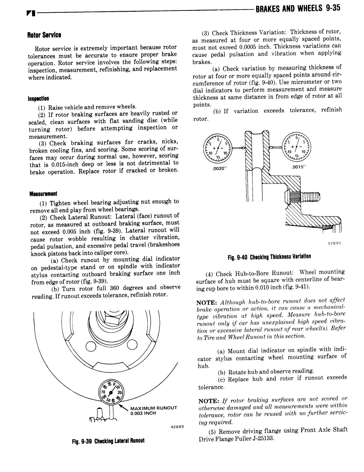
VI BRAKES ANI WHEELS 9 35 IIIl0I S rIIII 3 Check Thickness Variation Thickness of rotor i as measured at four or more equally spaced points Rotor service ls extremely lmpertant becsuse Yom must not exceed 0 0005 inch Thickness variations can mlesssees must be efeusste W ensure Proper brake cause pedal pulsation and vibration when applying operation Rotor service involves the following steps bi 8kes inspection measurement refinishing and replacement ai Cnsck Variation by msssnning ininknsss nf where dl 8l ed rotor at four or more equally spaced points around cir cumference of rotor fig 9 40 Use micrometer or two dial indicators to perform measurement and measure I thickness at same distance in from edge of rotor at all 1 Raise vehicle and remove wheels points 2 if rotor braking surfaces are heavily rusted or b If variation exceeds tolerance refinish scaled clean surfaces with flat sanding disc while rotor turning rotor before attempting inspection or measurement Q Q 3 Check braking surfaces for cracks nicks broken cooling fins and scoring Some scoring of sur faces may occur during normal use however scoring that is 0 015 inch deep or less is not detrimental to brake operation Replace rotor if cracked or broken ooz0 uo1s II mr n m g 1 Tighten wheel bearing adjusting nut enough to remove all end play from wheel bearings Y 2 Check Lateral Runout Lateral face runout of rotor as measured at outboard braking surface must Q not exceed 0 005 inch fig 9 39 Lateral runodt will cause rotor wobble resulting in chatter vibration pedal pulsation and excessive pedal travel brakeshoes msgs knock pistons back into caliper core a Check runout by mounting dial indicator FIg 9 AlI Ghwklng Thlckms varlatlan on pedestal type stand or on spindle with indicator stylus contacting outboard braking surface one inch 4 Check Hnb i 0 Bni s Runnin Wnssi mounting mm edge of r rmg 939 surface of hub must be square with centerline of bear b Turn rotor full 360 degrees and observe mgcup bore in within 0 0i0incn fig 9 4i reading If runout exceeds tolerance refinish rotor NOTE Although hub to bore runout does not affect broke operation or action it can cause c mechanical type vibration dt high speed Measure hub to bore runout only if car has unexplained high speed vibra tion or excessive lateral runout of rear u heel s Refer O to Tire and Wheel Runout in this section O a Mount dial indicator on spindle with indi cator stylus contacting wheel mounting surface of hub b Rotate hub and observe reading 8 c Replace hub and rotor if runout exceeds ii tolerance zo NOTE If rotor broking surfaces are not scored or l I x i m iRUN U otherwise damaged and all measurements were within 4 tolerance rotor con be reused with no further servic 428 as ing required 5 Remove driving flange using Front Axle Shaft F 9 39 Clicking MINI MMIII Drive Flange Puller J 25133