Ford Parts Wiki | GM Parts Wiki
Home | Search | Browse | Marketplace | Messages | FAQ | Guest
|
Technical Service Manual January 1975 |
|
Prev
 Next
Next
142298
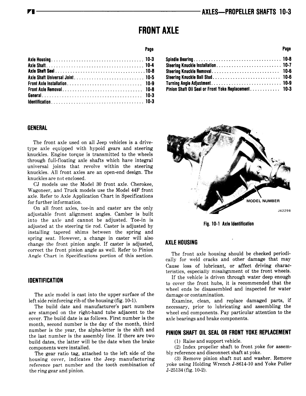
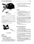
VI AXLES Pl10 ElLEI1 SNAFTS 10 3 FI10NT AXLE Page Faqs AxI llouslnu 4 4 10 3 Spindle Burlng 4 4 4 10 11 Axle Shall 4 4 104 Slnurlng Knuckle litmllatlan 4 4 I0 7 AxI Shall Sul 4 4 4 4 10 0 Smrlng llnuclila ll muvaI 4 4 4 4 10 0 Axln Snail llnivarsal Julnl 4 10 5 Staring l nuckI Ilall Sluil 4 4 Ill 8 Front Axla Installallun l 10 9 Turnlnq Anql Ailluslmsnl l l 4 10 9 From Axl llmuval 10 I Pinlun Shah 0Il Sul ur Frunl inks l1 plan n nl 10 3 Gnnnral l 4 10 3 Iilantlllutlun 10 3 GENERAL mz ty i u The front axle used on all Jeep vehicles is a drive Q il type axle equipped with hypoid gears and steering S V knuckles Engine torque is transmitted to the wheels 4 through full floating axle shafts which have integral universal joints that revolve within the steering e r knuckles All front axles are an open end design The knuckles are not enclosed j CJ models use the Model 30 front axle Cherokee i Wagoneer and Truck models use the Model 44F front V axle Refer to Axle Application Chart in Specifications for further information V MODE NUMBER On all front axles toe in and caster are the only 142298 adjustable front alignment angles Camber is built into the axle and cannot be adjusted Toe in is adjusted at the steering tie rod Caster is adjusted by H 10 1 Am mnmlmlnn installing tapered shims between the spring and spring seat However a change in caster will also change the front pinion angle If caster is adjusted IXLE lmusmc correct the front inion an le as well Refer to Pinion Angle Chart in Slpeciricatagns portion of this section The front axle housing should be checked periodi cally for weld cracks and other damage that may Cause loss of lubricant or affect driving charac teristics especially misalignment of the front wheels If the vehicle is driven through water deep enough IDENTIFIBITIDN to cover the front hubs it is recommended that the wheel ends be disassembled and inspected for water The axle model is cast into the upper surface of the damage or contamination left side reinforcing rib of the housing fig 10 1 Examine clean and replace damaged parts if The build date and manufacturefs part numbers necessary prior to lubricating and assembling the BFE Smmlied 011 the FlKh h3 d tube d 1 to U15 wheel end components Pay particular attention to the cover The build date is as follows First number is the nxle been ings and brake components month second number is the day of the month third number is the year the alpha letter is the shift and the last number is the assembly line If there are two Pmmu SHAFT 0 SEA an mm YUKE REPLABEMENT build dates the latter will be the date when the brake 1 Raise and support vehicle components were installed 2 Index propeller shaft to front yoke for assem The gear ratio tag attached to the left side of the bly reference and disconnect shaft at yoke housing cover indicates the Jeep manufacturing 3 Remove pinion shaft nut and washer Remove reference part number and the tooth combination of yoke using Holding Wrench J 8614 10 and Yoke Puller the ring gear and pinion J 25134 fig 10 2