Ford Parts Wiki | GM Parts Wiki
Home | Search | Browse | Marketplace | Messages | FAQ | Guest
|
Technical Service Manual January 1975 |
|
Prev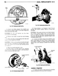

 Next
Next
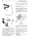
10 14 AXLES PI10PELLEl1 SllAFTS VI 12 Install retainer plate on axle shaft Toon 13 Apply wheel bearing grease to oil seal cavity M614 3 and between seal lips and install seal on axle shaft seal seat Outer face of seal must face axle flange 14 Before instllation pack bearing with wheel hearinggrease di 15 Install bearing on axle shaft Be sure cup rib I ring is facingaxle flange F 16 Install bearing retainer ring on axle shaft Z I 17 Using Flange Adapter J 25156 press new axle shaft bearing and retainer ring on axle shaft simul K i 0 taneously Tighten puller bolts alternately until bear i 10 ing and retainer ring are properly seated against shaft 1 shoulder 18 Install axle shaft through support plate using TOOL care not to damage axle housing tube inner oil seal J 8614 2 i C 19 Apply thin coating of wheel bearing grease to i outside diameter of bearing cup before installing in 1 bearing bore 1 ii gglsi 4 110 Tap end of flanged shaft lightly with rawhide mallet to position axle shaft bearing in bearing bore of F g z6 4iiiqy iig Rm Inky housing 111 Attach axle shaft retainer and brake support plate to axle tube flange Install attaching nuts and PIIIIGN SIIAFT 0IL SEAL 0I1 REAR YOKE REPLACEMENT lockwashers 112 Install cup plug in axle shaft flange hole S mi F i nn nh wi Tapgrgd Shan 113 Install brake drum spring type locknuts and W3 Wh l 11 Raise and support vehicle Remove rear wheels 14 Remove supports and lower vehicle and brake drums 2 Disconnect propeller shaft from rear yoke In dex shaft to yoke for assembly reference 13 Rotate drive pinion several revolutions Use mma Fun Float Shmmadalsol Companion Flange Nut Socket Tool J 22575 and an inch pound torque wrench to check torque required to NOTE It is not necessary to raise rear wheels in mm drive pinion order to remove rear axle shafts an Model 60 fitll fl0a i 19 3 V l NOTE The torque required to turn the drive pinion must be reeurded for reference at time of assembly 11 Remove axle flange nuts lockwashers and split washers retaining axle shaft flange fig 10 26 14 Remove pinion nut Use Companion Flange 12 Remove axle shaftfrom housing Holder and Remover Tool J 8614 1 or J8614 10 and Companion Flange Nut Socket Tool 22575 fig 10 26 Installa1mn FuII Floating Slim Modal 60 NOTE D 0 1 lZieiZ n3lZ i g 2 1fL 2 ZJiT b d 5 Mak pkt ad we page Shaft 0 aaaur B me 12 Install new flange onto hub studs recta lgnment at tlmeo fum y 1 10 3 InsertaxleShaftinmhousing 6 Remove rear yo e using tools J86 4 or J 8614 1 2 and 3 fig 10 26 17 Inspect seal surface of yoke lf surface is NOTE It will be necessary to rotate the axle shaft to damnged Oi gi owed replace yoke simultaneously align the shaft splines with the df 3 Remove pinion Oil Sea using Sen Remover ferentinl gear splines and the flange attaching holes 9233 fig 11 27 with the lWb tudS 19 Before installing replacement seal coat seal lip with rear axle lubricant 14 Install split washers lockwashers and flange 10 Install seal using Pinion Oil Seal Installer nuts Tighten nuts securely J 22661 fig 10 28