Ford Parts Wiki | GM Parts Wiki
Home | Search | Browse | Marketplace | Messages | FAQ | Guest
|
Technical Service Manual January 1975 |
|
Prev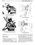
 Next
Next
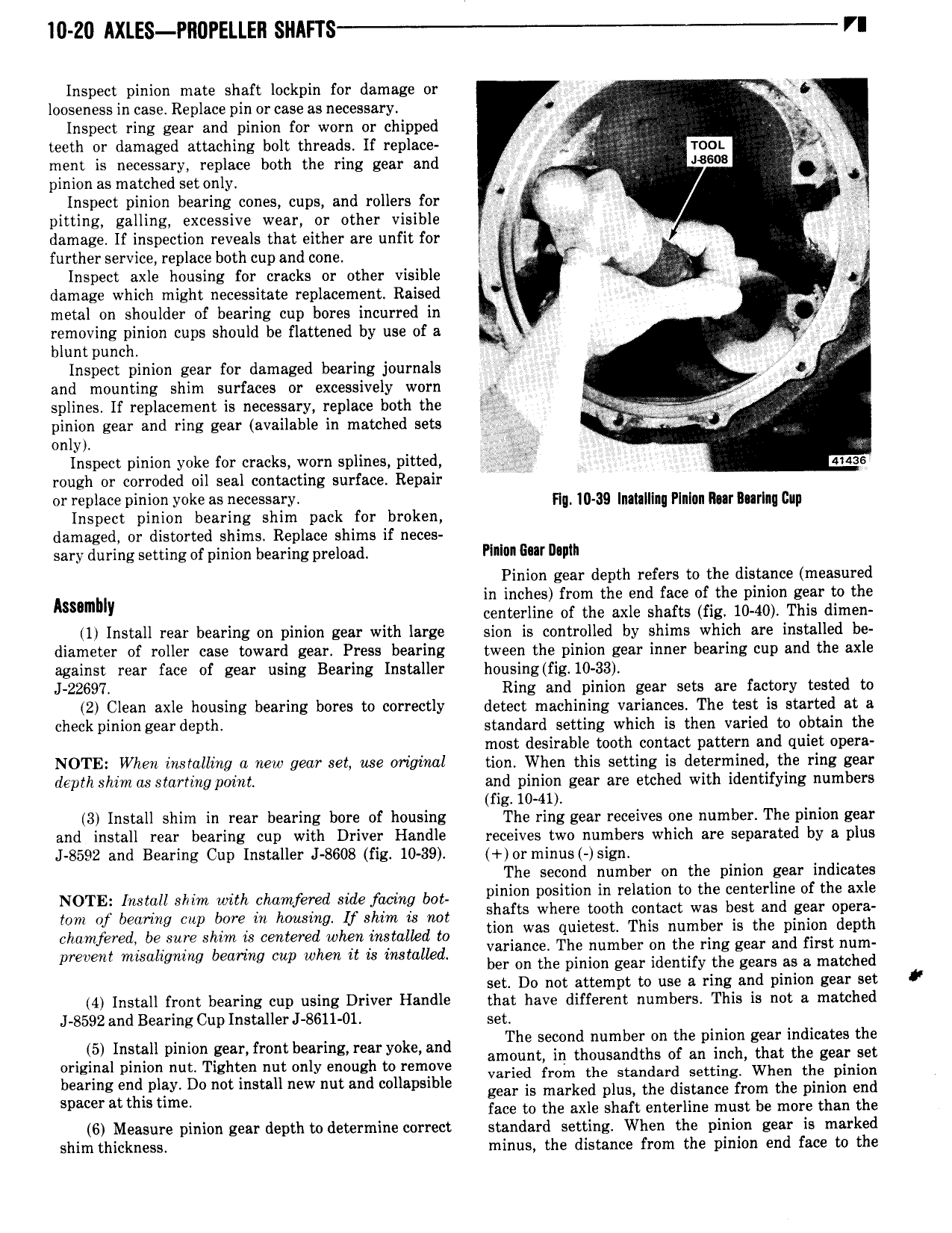
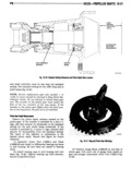
I0 Z0 AXLES PRUPELLEII SHAFl S VI Inspect pinion mate shaft lockpin for damage or Q looseness in case Replace pin or case as necessary Q i Inspect ring gear and pinion for worn or chipped 2 J A YL teeth or damaged attaching bolt threads If replace X mon ment is necessary replace both the ring gear and 8606 VL pinion as matched setonly i i Inspect pinion bearing cones cups and rollers for L pitting galling excessive wear or other visible I damage If inspection reveals that either are unfit for j 2 V J Q further service replace both cup and cone li W g i fj Inspect axle housing for cracks or other visible W W Y W damage which might necessitate replacement Raised Z metal on shoulder of bearing cup bores incurred in removing pinion cups should be flattened by use of a W n bluntpunch 5 r U Inspect pinion gear for damaged bearing journals J Q 0 and mounting shim surfaces or excessively worn gx D splines If replacement is necessary replace both the b be 7 T j i i nm m r pinion gear and ring gear available in matched sets W 4 Qent only Inspect pinion yoke for cracks worn splines pitted nano rough or corroded oil seal contacting surface Repair M or raplars pinion yaks as necessary Fla I0 39 Inainlllng Plnlun mr Baring cup Inspect pinion bearing shim pack for broken damaged or distorted shims Replace shims if neces sary during setting of pinion bearing preload Plllon Eur Illlllll Pinion gear depth refers to the distance measured Asumhl in inches from the end face of the pinion gear to the Y centerline of the axle shafts fig 10 40 This dimen 1 Install rear bearing on pinion gear with large sion is controlled by shims which are installed be diameter of roller case toward gear Press bearing tween the pinion gear inner bearing cup and the axle against rear face of gear using Bearing Installer housing fig 10 33 J 22697 Ring and pinion gear sets are factory tested to 2 Clean axle housing bearing bores to correctly detect machining variances The test is started at a check pinion gear depth standard setting which is then varied to obtain the most desirable tooth contact pattern and quiet opera NOTE When inslalling a new gear set use original tion When this setting is determined the ring gear depth shim aastarting point and pinion gear are etched with identifying numbers fig 10 41 3 Install shim in rear bearing bore of housing The ring gear receives one number The pinion gear and install rear bearing cup with Driver Handle receives two numbers which are separated by a plus J 8592 and Bearing Cup Installer J 8608 fig 10 39 or minus sign The second number on the pinion gear indicates 4 pinion position in relation to the centerline of the axle YZZTEZ iiZ ZEZZ 8Z ZZi KS3 ii L ZZZ sgeniwfi bij we Where MM g 2 a ry bat yd sia age chamfered be sure shim is centered when instalkd to zjxsygs lq 1 b r nI r5 gl e rea n t n m prevent mwahgmw bearmg cup www it is msmued ber on the pinion gear identify the gears as a matched set Do not attempt to use a ring and pinion gear set 4 Install front bearing cup using Driver Handle that have different numbers This is not a matched J 8592 and Bearing Cup Installer J 8611 01 set The second number on the pinion gear indicates the i5 Inimfll mmm Feanfront bearmgrear y k and amount in thousandths of an inch that the gear set g l T h y gh F varied rniin nin standard setting When nin pinion a d 1iy D0 s new an a gear ii marked plus nin distance from nin pinion end spacer at thm uma face to the axle shaft enterline must be more than the 6 Measure pinion gear depth todetermine correct standard setting When the pinion gear is marked shim thickness minus the distance from the pinion end face to the