Ford Parts Wiki | GM Parts Wiki
Home | Search | Browse | Marketplace | Messages | FAQ | Guest
|
Technical Service Manual January 1975 |
|
Prev
 Next
Next
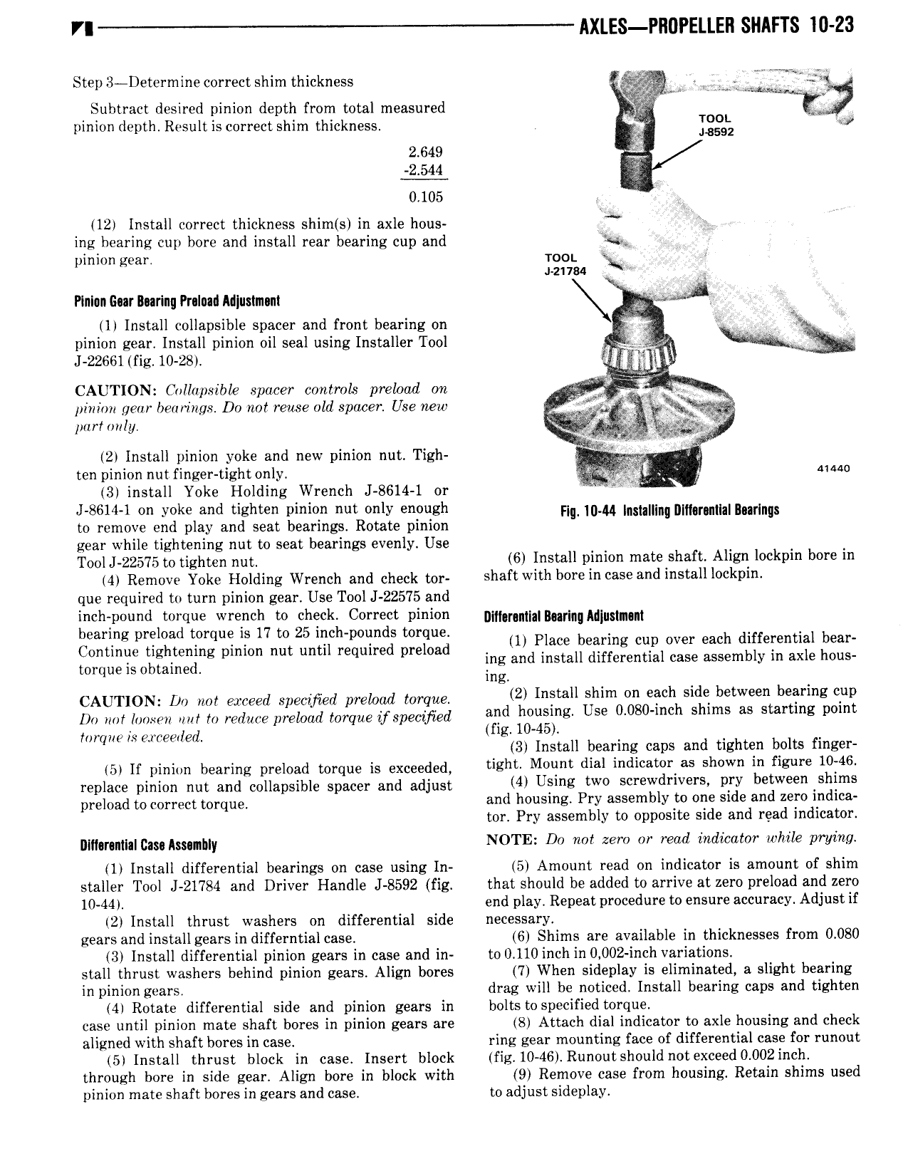
VI AXLES Pll0PELLEll SHAFTS 10 23 Step 3 Determine correct shim thickness 5 5 L ri r l Subtract desired pinion depth from total measured klglil pinion depth Result is correct shim thickness Ig ev 2 649 2 544 j 0 105 ex 12 Install correct thickness shim s in axle hous J s ing bearing cup bore and install rear bearing cup and Xl e V pinion gear moi z11a4 A Plnlcn Guar During Prnlnad M ustm m 2 4 3 1 Install collapsible spacer and front bearing on I V I pinion gear Install pinion oil seal using Installer Tool J 22651 fig 10 28 CAUTION Collapsible spacer controls preload on J W ill i J V pinion gear bearings Do not reuse old spacer Use new Q lutrtrmly 2 Install pinion yoke and new pinion nut Tigh M W Q ten pinion nut finger tight only t i 1 3 install Yoke Holding Wrench J 8614 1 or I J 8614 1 on yoke and tighten pinion nut only enough nl 10 44 Inmlung glndmmllnmlngs to remove end play and seat bearings Rotate pinion gear while tightening nut to seat bearings evenly Use Tool J 22575 to tighten nut 6 Install pinion mate shaft Align lockpin bore in 4 Remove Yoke Holding Wrench and cheek my shaft with borein case and install lockpin que required to turn pinion gear Use Tool J 22575 and Lnchipound ltogque wrench7 to ggieckil Correft pinion n jg Burma Mpmmm earing pre oa torque is 1 to inc p0un s torque Continue tightening pinion nut until required preload 1 glam Eiirlng mlplover Each dljfeilentl semi mrqueis Obtained ing and lnsta ifferentia case assem y in ax e ous ing CAUTION Do not exceed spectfied preload torque 2 l t ll shim on each side between bearing eup Do not 1U m to to reduce Wilma loqteospeoyor and l S s Us 0 08 h slum as St m torque is erceetled fl l0 45l 3 Install bearing caps and tighten bolts finger 5 If pingdn bearing preload torque is exceeded tight Mount dial indicatonas shown in figure 10j46 replace pinion nut and collapsible spacer and adjust 4 Using two screwdrivers pry between shims preload weeryeet mrdue and housing Pry assembly to one side and zero indica tor Pry assembly to opposite side and read indicator p 1 m m Ammjdy NOTE Do not zero or read indieator while prying 1 Install differential bearings on case using In 5 Amount read on indicator is amount of shim staller Tool J 21784 and Driver Handle J 8592 fig that should be added to arrive at zero preload and zero 10 44 end play Repeat procedure to ensure accuracy Adjust if 2 Install thrust washers on differential side necessary gears and installgearsin differntial case 6 Shims are available in thicknesses from 0 080 3 Install differential pinion gears in case and in to 0 110 inch in 0 002 inch variations stall thrust washers behind pinion gears Align bores 7 When sideplay is eliminated a slight bearing in pinion gears drag will be noticed Install bearing caps and tighten 4 Rotate differential side and pinion gears in bolts to specified torque case until pinion mate shaft bores in pinion gears are 8 Attach dial indicator to axle housing and check aligned with shaft bores in case ring gear mounting face of differential case for runout 5 Install thrust block in case Insert block fig 10 46 Runout should not exceed 0 002 inch through bore in side gear Align bore in block with 9 Remove case from housing Retain shims used pinion mate shaft bores in gears and case to adjust sideplay