Ford Parts Wiki | GM Parts Wiki
Home | Search | Browse | Marketplace | Messages | FAQ | Guest
|
Technical Service Manual January 1975 |
|
Prev
 Next
Next
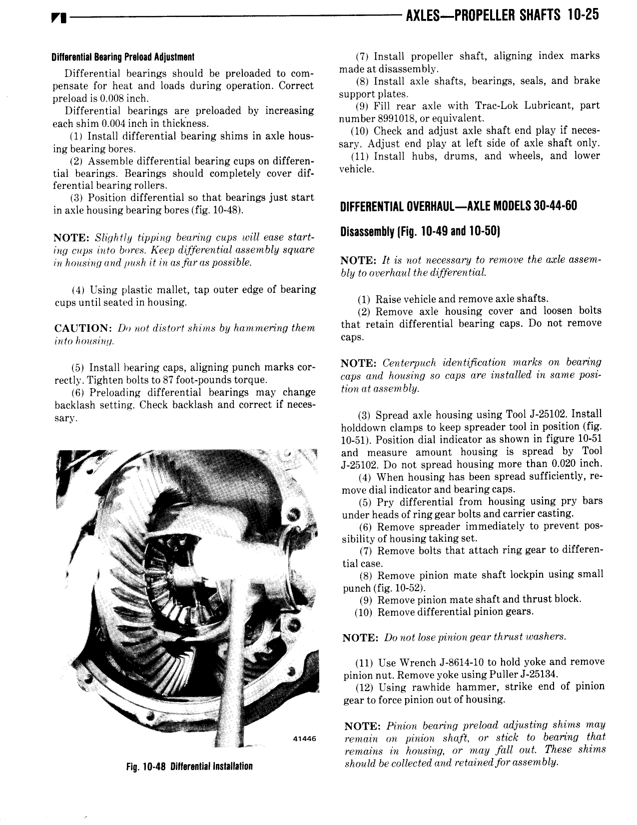
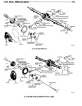
VI lIXLES PROPELLE I SHAFTS I0 Z5 Dllflrlntlllllatrlng Praltml Mlusimnnt 7 Install propeller shaft aligning index marks Differential hearings should be preloaded to com meds atdlsnssgmbln pensate for heat and loads during operation Correct lll lnslall alle l nflS l al ln S Sealsi and brake preload is 0 008 inch Support lllat S 4 Differential bearings are preloaded by increasing 9 Flll lean axle lvllll Tl a l l l l l l an Pint each shim 0 004 inch in thickness number 899l0l8 On ellulvalenl 1 Install differential bearing shims in axle hous lll Check and nlllllsl axle sllafl End play if neces ing bearing b m s sary Adjust end play at left side of axle shaft only 2 Assemble differential bearing cups on differen llll lnslall l lllS lll lms and Wll l lS and l w9l tial bearings Bearings should completely cover dif l l ll l9 ferential bearing rollers 3 Position differential so that bearings just start in axle housing hearing bores fig io 4g DIFFERENTIAL 0VEIIIIlI L AXLE M0l ElS 30 44 60 NOTE Slightly tipping bearing cups will ease start Dlslsnnmllly IFlg mdlg allll l0 5m ing cups into bores Keep differential assembly square in housing and push it in asfaras possible NOTE It is not necessary to remove the axle assent bly to overhaul the dweren tial 4 Using plastic mallet tap outer edge of bearing cups until seated in housing 1 Raise vehicle and remove axle shafts 2 Remove axle housing cover and loosen bolts CAUTION D my dgsyory ghims by mmme ing them that retain differential bearing caps Do not remove in to honsiny P 5 Install bearing caps aligning punch mm ks my NOTE Centerpnch identmcotion marks an bearing r ct y Tgghten bolts to 87 foogpounds mrqug caps and housing so caps are installed in same posi 6 Preloading differential bearings may change llnll fltassenlbly backlash setting Check backlash and correct if neces sary 3 Spread axle housing using Tool J 25102 Install holddown clamps to keep spreader tool in position fig 10 51 Position dial indicator as shown in figure 10 51 l gw no RJ fe and measure amount housing is spread by Tool vn ais LQ J 25102 Do not spread housing more than 0 020 inch 1 s W Spb 4 When housing has been spread sufficiently re g gl f Y move dial indicator and bearing caps W l x 5 Pry differential from housing using pry bars I a tit under heads of ring gear bolts and carrier casting q Y 6 Remove spreader immediately to prevent pos K sibilityofhousing taking set x 4 7 Remove bolts that attach ring gear to differen N g if l tial case VI f V T 8 Remove pinion mate shaft lockpin using small V g Y i punch fig 10 52 JL 9 Remove pinion mate shaft and thrust block r V 1 W 10 Remove differential pinion gears sl air A NOTE Dv not losepinian gear thrust washers Y 11 Use Wrench 8614 10 to hold yoke and remove g 4 y pinion nut Remove yoke usingPullerJ 25134 4 12 Using rawhide hammer strike end of pinion 1 gear to force pinion out of housing er I NOTE Pinion bearing preload adjusting shims may j 41446 remain on pinlknz shaft or stick to bearing that remains in housing or may fall out These shirns F g 1043 n t mpti n g g giy should be collected and retained for assembly