Ford Parts Wiki | GM Parts Wiki
Home | Search | Browse | Marketplace | Messages | FAQ | Guest
|
Technical Service Manual January 1975 |
|
Prev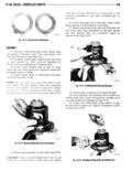
 Next
Next
142338
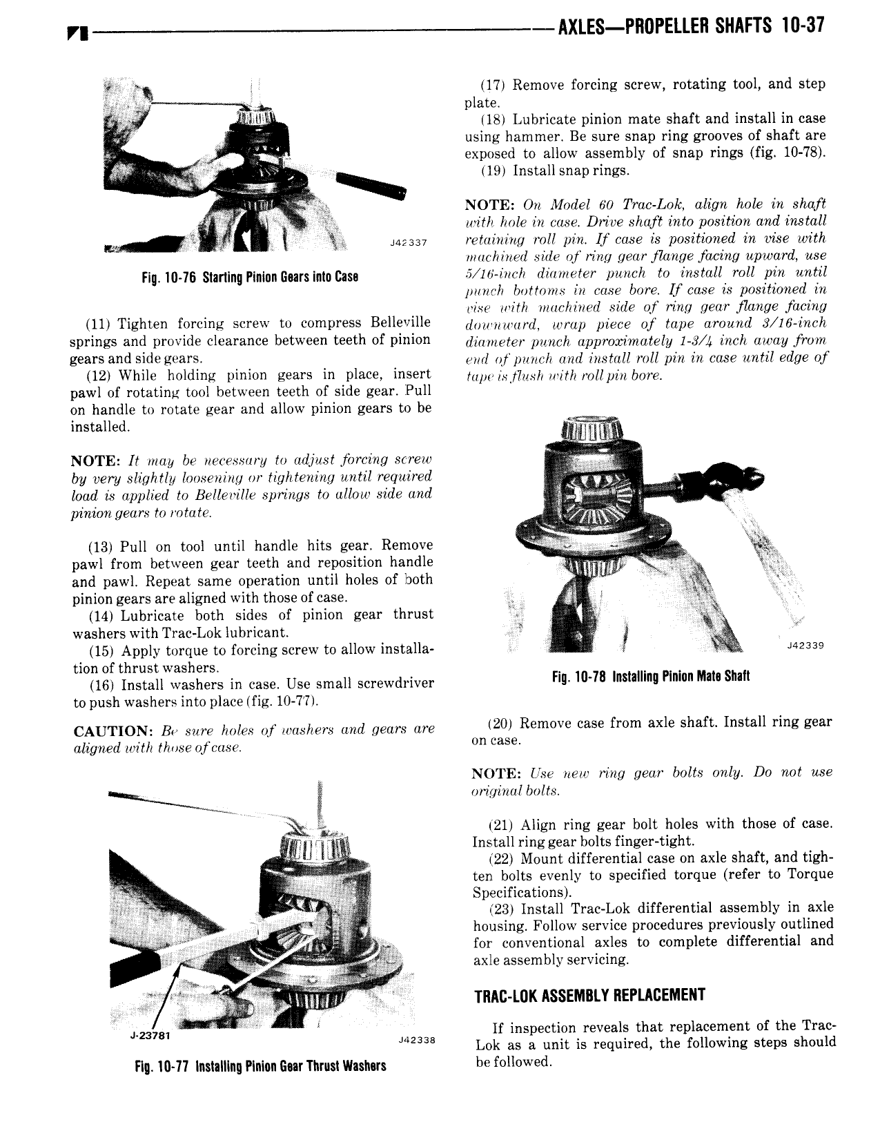
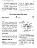
r AXLES PROPELLEH SHAFTS 10 37 QE 17 Remove forcing screw rotating tool and step plate V l l 18 Lubricate pinion mate shaft and install in case Q IL using hammer Be sure snap ring grooves of shaft are exposed to allow assembly of snap rings fig 10 78 19 Installsnap rings NT 1iT NOTE On Model 60 Trac Lok align hole in shaft 5 y 3 unth hole in case Drive shaft into position and install QJ I I iazsav retaining roll pin If case is positioned in oise with marhinerl sale ot ring gear flange facing upward use F g 10 16 sm lingP n gn g r i n g 5 16 inch diameter punch to install roll pin until punch lyottmns in case bore I case is positioned in q risc with machined side of ring gear flange facing 11 T sh e fprcms screw w wmprsss Bell vglle l1in nu n d only piece of tape mana 3 16 inch SPNHBS and DY 0V1d Clearance b W teeth of Dlmon diameter punch approximately 1 3 4 inch away from gears and Side H 31 4 eval of punch and install roll pin in cose anti edge of 12 While holdme wnwn gears in place msert ann izlyiusii aim rollpin img paw of rotating tool between teeth of side gear Pull on handle to rotate gear and allow pinion gears to be t ll d ms a e lv r u NOTE It may be necessary to adjust forcing screw A by very slightly loosening or tightening until required Y I loud is applied to Belleville springs to allow side and pinion gears tn rotate ji qmgg 13 Pull on tool until handle hits gear Remove pawl from between gear teeth and reposition handle e Mmm Q A and pawl Repeat same operation until holes of both 4 V Ji pinion gears are aligned with those of case 2 i 1 z 14 Lubricate both sides of pinion gear thrust RQ zi washers with Trac Lok lubricant y i 15 Apply torque to forcing screw to allow installa 4 J42339 tion of thrust washers 16 Install washers in case Use small screwdriver F ll 78 Insmllnll Plm Mm sum to push washers into place fig 10 77 CAUTION Bo me holes of nmilm limi gem are M20 Remwe me fmm axle Shaft 1 11 i z wr aligned with those ofcosc lm case NOTE Live new wing gear bolts only Do not use N I maint alia i 21 Align ring gear bolt holes with those of case in tlg Brig Install ring gear bolts finger tight f zl 22 Mount differential case on axle shaft and tigh O i ZYQ ten bolts evenly to specified torque refer to Torque igigtk Specifications I Yi i 23 Install Trac Lok differential assembly in axle jg 4 if 4 housing Follow service procedures previously outlined Tw 2 A ei r f V fi0 al axles to complete differential and i 2 i J if axle assembly servicing r Qc rf M E 4 Aly mj I TMC LDK ASSEMBLY REPLACEMENT 1 t i amy V W if inspection reveals that replacement of the Trac 1 142338 Lok as a unit is required the following steps should Fly I0 l l lnslalllng Plnlnn Snr Tnrusl lllaslms be f ll W d