Ford Parts Wiki | GM Parts Wiki
Home | Search | Browse | Marketplace | Messages | FAQ | Guest
|
Technical Service Manual January 1975 |
|
Prev
 Next
Next
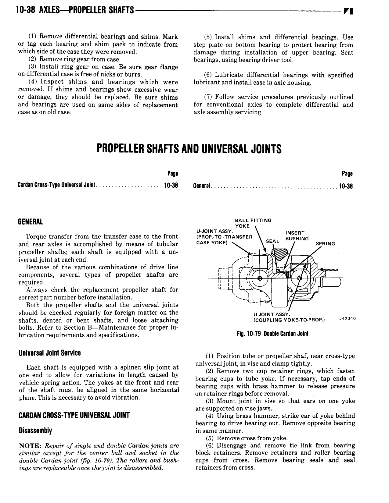
I0 38 AXLES PIIOPELLEII SHAFIS r 1 Remove differential bearings and shims Mark 5 Install shims and differential bearings Use or tag each bearing and shim pack to indicate from step plate on bottom bearing to protect bearing from which side ofthe casethey were removed damage during installation of upper bearing Seat 2 Remove ring gear from case bearings using bearing driver tool 3 Install ring gear on case Be sure gear flange on differential case is free ofnicks or burrs 6 Lubricate differential bearings with specified 4 Inspect shlms and bearings which were lubricantand install case inaxlehousing removed If shims and bearings show excessive wear or damage they should be replaced Be sure shims 7 Follow service P 0 d D Vl lY outlined and bearings are used on same sides of replacement for conventional axles to complete differential and case as on old case axle assembly servicing PIIUPELLEII SHAFTS MID UNIVERSAL JIJIIITS Pm Pm Gardan Grass Type l nIv rsaI Julnl e I 38 G n raI r r r lll 38 GENERAL agi Frrrmc u mum Assv WSERT Torque transfer from the transfer case to the front race 10 rmamssza EUSHWG and rear axles is accomplished by means of tubular CASE V KEl SEA SPRING propeller shafts each shaft is equipped with a un iversaljointat each end I Q Because of the various combinations of drive line T rf 74 T7 4lr components several types of propeller shafts 81 0 I I required II I Always check the replacement propeller shaft for 1 by 5 g correct part number before installation l Both the propeller shafts and the universal joints I should be checked regularly for foreign matter on the U 0rNy Assy shafts dented or bent shafts and loose attaching couruuc v0 s r0 PROP 23 bolts Refer to Section B Maintenance for proper lu brication requirements and specifications HIL 10 79 DWI umin JM unlvusal mlm sarvlm 1 Position tube or propeller shaf near cross type universal joint in vise and clamp tightly Each Shan S e W2 l d 10 at or Rerrrere two err retainer rrree which fasten one end to allow for variations in length caused by bearing cups to tube yoke If necessary tap ends of vehicle spring action The yokes at the front and rear bearing cups with brass hammer to release pressure of the shaft must be aligned in the same horizontal on retainer rings before removal plane This is necessarytoavoid vibration 3 Mount joint in Visa so that ears on one yoke are supported on visejaws CAIIDAN 2IIOSS TYPE UNIVERSAL JOINT 4 Using brass hammer strike ear of yoke behind II bearing to drive bearing out Remove opposite bearing DISISSOII ly in same manner 5 Remove cross from yoke NOTE Repair of single and double Carclan joints are 6 Disengage and remove tie link from bearing similar except for the center ball and socket in the block retainers Remove retainers and roller bearing drmbk Carden joint mg 10 79 The rollers and bush cups from cross Remove bearing seals and seal ings are replaeceubk once the joint is disassembled retainers from cross