Ford Parts Wiki | GM Parts Wiki
Home | Search | Browse | Marketplace | Messages | FAQ | Guest
|
Technical Service Manual January 1975 |
|
Prev

 Next
Next
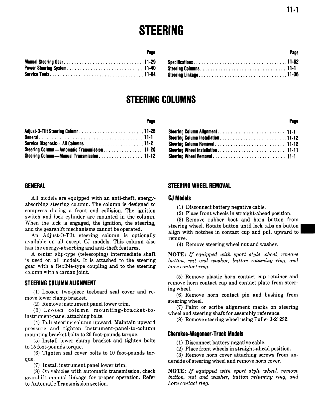
11 1 P 11 Pm lllanul 81 rIn Eur 11 29 Spsnlllullons 11 62 Pnuur Slurlng Syria 4 4 11 40 Sl rIn Column 11 1 Sorvlna Ynuls 4 11 84 Smrlnq Llnlups 4 11 36 Pap Pm A1l u l 0 TIII Smrlnn Column 4 4 11 25 Smrlnq Colunn AII m nt 1 11 1 G n rsI 11 1 Smrlnq Column lnslsllnlon 11 12 Ssrvlcn Alll Il l lS All Column 4 11 2 Smrlnq Column llmuual 4 4 11 12 Sl rIn Column Aulomailc Tnnainlsslan 4 11 20 Staring VIl1 l InmII lI n 11 11 Si rIn Column ltnual Tnnsnnlsslon 11 12 Smrlng Vll I Runml 11 1 GENERAL STEERING WNEEL REMOVAL All models are equipped with an anti theft energy cd I l l8 absorbing steering column The column is designed to 1 Disconnect buttery ne ative cable compress during a front end collision The ignition 2 Plncefmntwheelstn imighpahend position switch and lock cylinder are mounted in the column 3 Remove rubber hoot and hum button num when the lm is ng g d the ig m n the steering steering wheel Rotate button until lock tabs on button and m 1 h m m nur wrt notches in contact up rrr pur upward to An Adjust O TiIt steering column is optionally remove available on all except CJ models This column also has the energy absorbing and anti theft features 4 Remove steering wheel nut and wash A center slip type telescoping intermediate shaft NOTE lf equipped with sport atyk wheel remove is used on all models It is attached to the steering button nut and washer button retaining ring and gear with a flexible type coupling and to the steering ham contact ring column with a cardan joint l 5 Remove plastic horn contact cup retainer and STEENINE COLUMN ALIGNINENT remole liorn contact cup and contact plate from steer lng W 99 m 7g g gg g wgtw M d 1 v md re up izuuuve 1 mtu pr and rrrrug rm 12 Rem m W m i Y I i l ruru ur r mr 0 1 W Loom column m i m wr r uu r r ur F rr rtrmrrt instrument panel attaching bolts 8 R tie h I li n rJ 21n32 4 Pull steering column upward Maintain upward Emwes rmgw ee usmg u e pressure and tighten instrument panel to column mounting bracket suits to 20 rmt pounds torque Ch rok Wagasar Truck IlIu l I 5 Install lower clamp bracket and tighten bolts 1 Disconnect battery negative Mbit w 15 f t p dS rq 2 Place front wheels in straight ahead position q 6 Tlghwn s l V b It t 10 f t p d wl 3 Remove horn cover attaching screws from un d d i te h 1 d h 7 Install instrumentpanel lower trim em en S ermgw ee m remove Om cover S On vehicles with automatic transmission check NOTE Lf equipped with sport styk whceL remove gearshift manual linkage for proper operation Refer button nut and washer button retaining ring and to Automatic Transmission section hom contact ring

 Next
Next