Ford Parts Wiki | GM Parts Wiki
Home | Search | Browse
|
Technical Service Manual January 1975 |
|
Prev
 Next
Next
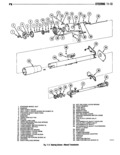
11 12 STEER NG VI g Q M REMQVAL 2 Align scribe marks on steering shaft and lun iversa joints Install universal joint pinch bolt Tigh cnorioivt mon removed from no vehicle monte ten pinch hcitw f t 1 hd t r c the column with special care Sharp blows on the end 3 Pull steetflng column Pw d Mftmtam upward af the Steennn Shaft 0 Sam levers waning an me pressure and tighten eolumn mounting bracket to ealanln a Sen bla 0 ammnng me assembly Conga instrument panel attaching nuts to 20 foot pounds tor shear or loosen the plastic fasteners that maintain 1 column rigidity CAUTION Do rwt ouertighten bolts and nuts Cor in Discchhcct battery negative c I rect torque on bolts and nuts is necessary to ensure 2 Disconnect steering column wiring connectors breakaway aenan Ofeagamn bnackemnd capsnlen from wiring harness and ignition switch NOTE Steering wheel does not have to be removed 4 I St llt0 b 3 d Pi 1 t5 ta nenmne Steengng w nmn 5 Connect all electrical components and check for proper operation 3 Scribe alignment marks on steering shaft and 6 Install instrument panel trim steering column universal joints for assembly reference bezel and left side air conditioning duct if equipped 4 Disconnect steering column gearshift linkage 7 On vehicle with automatic transmission check from shift lever on automatic column shift models gearshift manual linkage for proper operation Refer 5 Remove column to toeboard parts to Automatic Transmission section 6 Remove lower instrument panel trim steering 8 Connect battery negative cable column bezel left side air conditioning duct if equip ped and column to instrument panel bracket stud t5 i b ltSl STEERING DULIIMN IMNIIAL TRANSMISSION 7 Remove bracket to column bolts and remove column mounting bracket nmsumnly CAUTION Set bracket aside to protect breakaway eapsagen Column removal is not necessary if only the anti theft cover lock plate and snap ring cancelling cam NOTE Bracket capsules on slotted topermit column turn signal switch buzzer switch ppcr he rinz movement for adjustment nearing or lock cylnnder are ntlonbe sgrviegd fincgl ii e co umn mus e remove in or er serv 8 Remove column from vehicle of lE t Ktm l l 8 QmP0 t5a the column w e co umn is remove remove instrument panel mounting bracket fig 11 3 install STEEMNG column INSTIIUTIIIN Support Fixture J 23074 fig 11 4 and mount column in vise b clam ing flange of support fixture in vise WARNING Use Mtv specified screws belts and i pim frd nt wnooii in straight ahead position nuts wm servicing the column and tighten only to Disconnect bntteny negative cable the speci icd tvniuc to maintain the e mru ab vrI inv 2 Cover pointed mos or column compression action of the steering column Bolts 3 Remove s eH jngwh o tower than i ccifc i i n niet not be Med as they 4 Loosen anti theft tovoi retaining wows and may PWM the l tm t fran 0 mP 5 i 9 WWW im lift cover from column fig 11 5 It is not necessary to Pact The mils W mts S I l 9 the column nwnttna completely remove these screws as they are held on bracket to the instrument panel must be tightened to cover by nlnmc retainers the proper torque so that the bracket will break away 5 Use Lack Plate Compressor Tool 1 23658 to undertmpaote compress lock plate and unseat round wire snap ring from steering wheel shaft groove fig 11 6 1 Attach column mounting bracket to column Tighten bolts to 15 f ot pounds torque WARNING Lack plane Le under www Spring ml CAUTION Do not use substitute bolts Position sw column and loosely attach column to instrument panel with rear attaching studs at mounting bracket Be 6 Remove lock plate compressor tool sure that column instrument panel mounting is never 7 Remove snap ring lock plate turn signal unsupported when either dash mounting or gear canceling cam upper bearing preload spring and mounting is connected thrust washer from steering shaft