Ford Parts Wiki | GM Parts Wiki
Home | Search | Browse
|
Technical Service Manual January 1975 |
|
Prev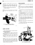
 Next
Next
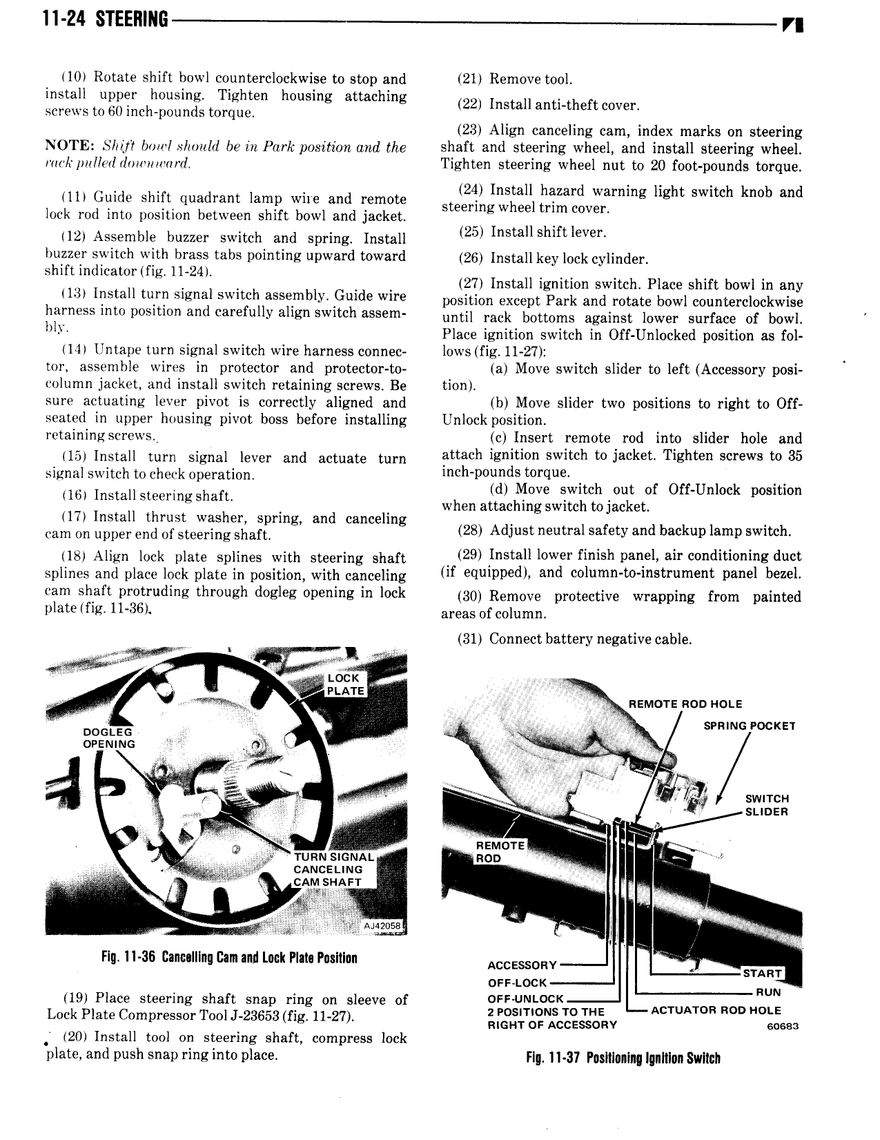
11 Z4 STEERING VI 110 Rotate shift bowl counterclockwise to stop and 21 Remove tool install upper housing Tighten housing attaching 22 Install anelnheft coverl screws to 60 inch pounds torque 23 Align canceling cam index marks on steering NOTE Shy boi1 Ixh1 uld be in Park position and the shaft and steering wheel and install steering wheel rmi rpullwl 1o w i1 ard Tighten steering wheel nut to 20 foot pounds torque 24 I 1ii o ae an W i lamp we an em stgernygjljgylg g j j3 hgh Sim knob and lock rod into position between shift bowl and jacket 112 Assemble buzzer switch and spring Install 25 Install Shlftleveh buzzer switch with brass tabs pointing upward toward 26 Install key lock cylinder Shift mdlcamr fIg II MI 27 Install ignition switch Place shift bowl in any 113l Install turn signal switch assembly Guide wire nosltlon oxoont park and potato bow countorclockwjse harness into position and carefully align switch assem nntil took bottoms against lower surface of bowt IlIl Place ignition switch in Off Unlocked position as fol 114 Untape turn signal switch wire harness connec lows fig 11 27 4 tor assemble wires in protector and protector to a Move switch slider to left Accessory posi column jacket and install switch retaining screws Be tion l sure actuating lever pivot is correctly aligned and b Move slider two positions to right to Off seated in upper housing pivot boss before installing Unlock position retaining screws c Insert remote rod into slider hole and ll5l lnstall turn Signal level and aetnate turn attach igmtnon switch to Jacket Tighten screws to 35 signal switch to check operation l h p l dv q B tch t f Off U 1 k t ove swi nu o n oc posi ion lb lnstax stljermg Shaflt d 1 when attaching switch tojacket 117 nsta t rust was er spring an cance ing Cam On upper and Ol steering shalt 28 Adjust neutral safety and backup lamp switch llgl Allan lock nlate Snllnes with ateerlng shalt l 29 Install lower finish panel air conditioning duct splines and place lock plate in position with canceling M equlppedh and Ium I s r m I panel bezel wm Shsft i r tr di e lhrvush desks p i s in lock 30 Remove protective wrapping from painted plate fig I1 36 areas of column 31 Connect battery negative cable etgg 1 i 0 PLATE i V g nsmor noo not A I et svnincrockzr noouzc V x W oeeumo t T a V f i wat or I N sw H stanza J I o E REMUYE l a Tum SIGNAL son cANcE iNo 1 cam swan 1 my sages l Flu 11 36 Canulllnu Cam and Luck Plain Pnsltlun Aootsson V sum oss Lock RUN 119 Place steering shaft snap ring on sleeve of FF JN cK Lock Plate Compressor Tooi massa rig 11 27 j g fC s fm 201 Install tool on steering shaft compress lock plate and push snap ring into place FI II 37 P1 sII 01IIM IlI1I1I II SVIIIGII