Ford Parts Wiki | GM Parts Wiki
Home | Search | Browse
|
Technical Service Manual January 1975 |
|
Prev

 Next
Next
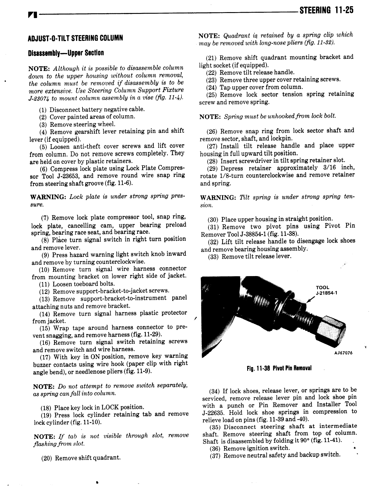
r STEE11ING 11 25 ADJUST 0 TlLT STEERING COLUMN N0TE Qwwlmnl is retained by e amino clip which may be removed with long nose pliers jig 11 92 I1I m nllly lIpp r Sacllnn A 21 Remove shift quadrant mounting bracket and NOTE Although it is possible to comrontlo opznptp hem Socket if eapivvedl clown to the upper housing without column removal 22 Removotlltreleese handle the column must be removed if disassembly is to be 23 Remove thm upper COW Wni 8 W more extensive Use Steering Column Support Picture 24 Tap Plm V from l m pg0yl to mollnl oolnmn oosemely ln o me me 11 25 Rsmove lock sector tension spring retaining crew an remov rln 1 Disconnect battery negative cable S e sp E 2 Cover painted mas of o m NOTE Spring must be nplookecjrom lock bolt 3 Remove steering wheel 4 Remove gearshift lever retaining pin and shift 26 Remove Snap ring from lock sector Snnft and l V if l1 1DP d remove sector shaft and Iockpin 5 Loosen antl theft cover screws and lift cover 27 Install tilt neleene nnndle and place upper from column Do not remove screws completely They nonelnggn full upward lll position are held on cover by plastic retainers 28 Insert screwdriver in tilt spring retainer slot 6 Compress lock plate usme Lock Plow Comoros za Depress retainer approximately s 16 inch r 1 l J 23653 end remove mlmd wire l rms rotate 1 B turn counterclockwise and remove retainer from steering shaft groove fig 11 6 and spring LgNIN Mk Plate it mer Mov wing rm wmtmucr rin spring ir under mpg spring ton sion I 7 Fiemcve plate compressurbwolf Snap ring 30 Place upper housing in straight position P 3 m mg wml pP r earmg pm 31 Remove two pivot pins using Pivot Pin spring bearing race seat and bearmgerace Remover Tool J 38854 1 fig 1138 8 M lm S Wh in mm or Lift tilt rel erre handle to alarm not that and removelevel drem ve bearin housin assembl 9 Press hazard warning light switch knob inward an 33 15 I y and remove by turning counterclockwise emove tl re ease eval 10 Remove turn signal wire harness connector from mounting bracket on lower right side of jacket 11 Loosen toeboard bolts 12 Remove support bracket to jacket screws M 00 13 Remove support bracket to instrument panel new 2 BSM attaching nuts and remove bracket Wi V 14 Remove turn signal harness plastic protector from jacket i O r47 j Q 15 Wrap tape around harness connector to pre l f vent snagging and remove harness fig 11 29 16 Remove turn signal switch retaining screws and remove switch and wire harness r 17 With key in ON position remove key warning 67 76 buzzer contacts using wire hook paper clip with right angle bend or needlenose pliers rip 11 ol Flu 11 3 PM Pin Mlm NOTE Do not attempt to remove switch separately assorirtg canfall into column 34 If lock shoes release lever or springs are to be serviced remove release lever pin and lock shoe pin 18 Placekey lock in LOCK position with a punch or Pin Remover and Installer Tool 19 Press lock cylinder retaining tab and remove J 22635 Hold lock shoe springs in compression to lock cylinder fig 11 10 relieve load on pins fig 11 39 and 40 35 Disconnect steering shaft at intermediate NOTE if lab is not visible through slot remove shaft Remove steering shaft from top of column flashing from slot Shaft is disassembled by folding it 90 fig 11 41 36 Remove ignition switch r 20 Remove shift quadrant 37 Remove neutral safety and backup switch

 Next
Next