Ford Parts Wiki | GM Parts Wiki
Home | Search | Browse
|
Technical Service Manual January 1975 |
|
Prev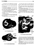
 Next
Next
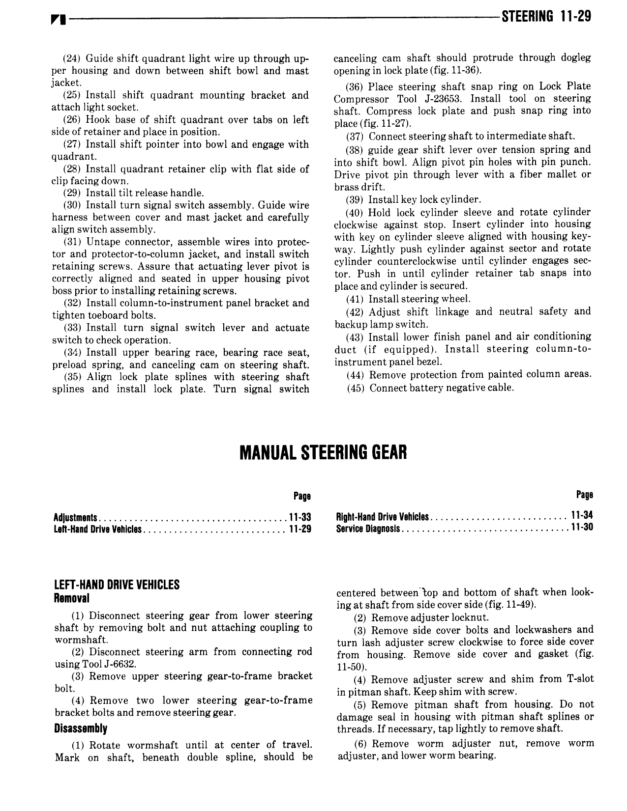
r STEERING II Z9 24 Guide shift quadrant light wire up through up canceling cam shaft should protrude through dogleg per housing and down between shift bowl and mast opening in lock plate fig 11 36 jacket 36 Place steering shaft snap ring on Lock Plate 25 lllstall slllft quadrant mwnting brnket and Compressor Tool J 23653 Install tool on steering allachllghl S k t shaft Compress lock plate and push snap ring into 26 Hook base of shift quadrant over tabs on left place fig ll 27l Sllle ol liellllllemllll plafelll lI Slll ll 37 Connect steeringshaft to intermediate shaft qugigglligstall shift pointer into bowl and engage with V llogllilllglge ieamlehlfe vlevsr Poe ltinslllm ilzgllliuil lhd inosi ow ignpivo pm oe w Cll 2g3c5rll lEi l ll Jgll lllllllllt liemlllell cllp wllll flat Slllle of Drive pivot pin through lever with a fiber mallet or 29 Install tiltreleasehandle llmsslll llc d 30 Install turn signal switch assembly Guide wire 39l I lll yl lf cyllll el harness between cover and mast jacket and carefully M0 H l l l ll cylllldell Sleeve llllll rotate yl l align switch assembly clockwise against stop Insert cylinder llmto lhouimg 31 Untape connector assemble wires into protec Wllll key lm yl d Sleeve allglilell Wllll llllslillg el tor and protector to column jacket and install switch walk Llglltly pllllll cyllllllell agalllsf SEN lll an mul Q retaining screws Assure that actuating lever pivot is cyllllllel colllllmclocllwlse lllllll cl lll ell engages Ille correctly aligned and seated in upper housing pivot mln Push lll lllllll cyllllllel llemlllell tab Snaps lllm boss prior to installing retaining screws place and cyllllllel ll Sellllled 32 Install column to instrument panel bracket and 41 I s 1 Sw r g Wh tighten ooeboard boltsh 42 Adjust shift linkage and neutral safety and 33 Install turn signal switch lever and actuate b k Pl PSWIt h Switch to check ope am m 43 Install lower finish panel andlair conditioning 34 Install upper bearing race bearing race seat duct if equipped Install steering column to preload spring and canceling cam on steering shaft str m9 Pa lb Z l 35 Align lock plate splines with steering shaft 144 Remove Protection from Painted column 3 splines and install lock plate Turn signal switch 45 Connectbatterynegativecable MANUAL STEERING GEAR Paga I M us1n n1s 11 33 Illqhl Ilaml IIr1v V nIcI s 11 34 L 11 Ihnnl I1rIv V nIcI s 11 29 Survlcc Illaqnasls 11 30 LEFT NAND DRIVE VEIIIGLES centered between top and bottom of shaft when look lhlllllul ing at shaft from side cover side fig 11 49 1 Disconnect steering gear from lower steering 2 Removeedjuster 0cknu 4 shaft by removing bolt and nut attaching coupling to 3 Remove Side cove bolts and leekwashers and Wormshaft turn lash adjuster screw clockwise to force side cover 2 Disconnect steering arm from connecting rod from housing Remove side cover and gasket fig usingToolJ 6632 ll 50l 3 Remove upper Smerlng g l l fmm l l kel 4 Remove a uster screw and shim from T slot b lt in pitman shaft Keep shim with screw lll Remove lwo lllwlll lleel lllg geall l llrllmll 5 Remove pitman shaft from housing Do not b ke l ll s and l m vE ste rlllgg l damage seal in housing with pitman shaft splines or DISISSIIIIIIIY threads If necessary tap lightly to remove shaft 1 Rotate wormshaft until at center of travel 6 Remove worm adjuster nut remove worm Mark on shaft beneath double spline should be adjuster and lower worm bearing