Ford Parts Wiki | GM Parts Wiki
Home | Search | Browse
|
Technical Service Manual January 1975 |
|
Prev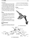
 Next
Next
r STEE11I1lG 11 35 1 Clean exterior of steering gear To remove needle bearings press them out using a 2 Remove filler plug from steering gear housing piloted mandrel To install new needle bearings press and drain lubricant from gear the bearing into the side cover or steering gear housing 3 Paint index marks on roller gear and shaft as so that the face of the bearing is flush with the bearing sembly on steering arm for correct alignment during boss of the cover or housing assembly Inspect the worm gear and shaft assembly visually 4 Remove nutand lockwasher from shaft for wear scoring or pitting If necessary polish ligh 5 Remove arm from shaft using pitman arm pu tly with a fine abrasive cloth Replace assembly if it is ler visibly worn or damaged Inspect upper and lower ball bearings and cups of CAUTION Do not use a hammer or wedge to re the worm gear and shaft assembly for wear and move steering arm from roller gear and shaft asserrl damage Replace if visibly worn or damaged bly This will damage gear and shaft assembly NOTE Bearing balls must be replaced as a full set in 6 Using fine file or emery cloth remove any each bearing nicks or burrs from exposed portions of roller gear and shaft assembly and from worm gear and shaft as sembly ISSOMIIIY 7 Rellllllle l l eltaclllllg capeclewsl Bldg el 1 Position new oil seals at wormshaft and roller and gasket l l lll Sleelnlllg gear ll Sl g when Vel ls gear shaft oil seal bores of steering gear housing with removed attached roller gear and shaft assembly can longer lin of each seal facing into housing eleo be wlllllllawll l l lll l l llslllg 2 Press each seal into housing using suitable Sl Remove l lllllltl l lll adjustment 5 l W diameter tool that will contact seal bore of housing 9 Turn screw clockwise until completely un around its entire perimeter threaded from side cover then remove roller gear and 3 Lubricate worm gear and shaft assembly and shall assembly lllelll Vel upper ball bearing and cup with Gear Lubricant 10 Remove four attaching capscrews and end Grade SAE g0W cover from steering gear housing 4 insmii bearing and cnn en Shan lll Remove vvoem Keel eml mole eeeemole lll Install shaft assembly in steering sssl housing ll Remove lover eml oooee oeeems eooe eml loell Be sllls spllllsll end of shaft llsss lla damage oil seal lleallngs ll l l Sll ll 6 Lubricate lower end of worm gear and shaft 13 Remllve w l ll l gear Shell ll eeel and l 0llel assembly and lower ball bearing and cup with Gear gear shaft oil seal from housing Discard both seals Lnbi icantGi ade SAE g0W 7 Install bearing cup and spacer on shaft 8 Install shims and end cover on steering gear ngpgg j n housing and install attaching bolts Tighten bolts hand tight only Clean all parts with cleaning solvent and wipe dry 9 Adjust bearing preload Inspect the steering gear housing for cracks breaks I0 Mount tapped hole of side cover on adjustment or other damage Replace if damaged screw of roller gear and shaft assembly Inspect the roller gear and shaft assembly for wear 11 Thread screw counterclockwise into cover until scoring or pitting If necessary polish lightly with s end of Shafllllst l l h Sll ll l l face of 0V l fine abrasive cloth Be sure roller gear has proper 12 Install locknut on adjustment screw hand freedom of movement and does not have excessive lash tight or roughness Replace gear and shaft assembly if visi 13 Install gasket on side cover bly worn or damaged 14 Lubricate gear of roller gear and shaft assem Check adjustment screw of roller gear and shaft as bly with Gear Lubricant Grade SAE 80W sembly for excessive end play If end play exceeds 15 lnS 1 lZ EGM and shaft 5S lnhlY in h llSlnE B9 0 015 inch remove the retaining ring thrust washer S 1l end of shaft does not damage 0ll Seal in h0ll9ll lK and screw from the gear and shaft assembly Replace 16 Roller gear and worm gear must mesh to seat the retaining ring if unserviceable Secure a new Side 0V9l to h0llSlhg adjustment screw and thrust washer in the gear and 17 Install cover to housing attaching bolts Tigh shaft assembly with a retaining ring ten bolts to 20 foot pounds torque Inspect needle bearings which carry roller gear and IB Adjust gear clearance shaft assembly in the side cover and the steering gear 19 Clamp Xn0S d section of roller EGM and shaft housing Replace if visibly worn or damaged Insert a assembly in vise shaft through each bearing and cheek for clearance If 20 Align index marks made during disassembly clearance exceeds 0 010 inch replace bearings and lnSl 3ll Steering arm on splined end of Shafts