Ford Parts Wiki | GM Parts Wiki
Home | Search | Browse
|
Technical Service Manual January 1975 |
|
Prev
 Next
Next
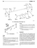
11 36 STEERING r 21 Install lockwasher and nut on shaft threads steering gear assembly It prevents gear wear result and tighten nut to draw arm into position on spline ing from insufficient backlash and steering play 22 Fill steering gear housing with Gear Lubricant which would result from excessive backlash Gear Grade SAE BOW backlash is adjusted by an adjustment screw which 23 Adjustments determines the longitudinal position of the roller gear mmm rr nmMlca1 m d bly I I d d 1 necessary oosen ocknut an turn a just apgllxz igeiggirgggg g Vl tl Stbg I 1 n i5 ment screw at the side cover counterclockwise until port the worm gem and Shaft assembly It is made by worm gear shaft turns freely through its entire range adding or subtracting shims from between the steer f tmvellflg u 59 inggear housingand end cover 2 Count number of turns necessary to rotate lf necessary loosen capscrews which attach the end Wvfm Bear shaft th 0uKh its mth range of l Y aV l tngglitht Steering uni hoaiiitz fist 11 ttl f t 3 Turn Start to center of ata travel en capscrews a erna e y an on a ew urns at a time while rotating the worm gear sllaft Tighten 4 Rota Shaft liack and forth thmdlgh center of screws to 20 tootpounds torque travel and tighten adjustment screw until shaft shows Check rolling torque required to rotate the worm shght bmd at center of tml el gear shaft When bearing preload is correct this tor 5 Adjust screw until rolling torque of 7 to 12 que will be 2 to 5 inch pounds If necessary remove inch pounds to rotate shaft through center of travel end cover Either add to or subtract from the number 6 Hom adjustment screw in positim and tighten of shims and repeat the above procedure to obtain locknutto18 mt p0undSmrque correct bearing preload 7 Recheck rolling torque necessary to rotate smrlm E clan Ml m worm gear shaft through center of its travel If neces This steering gear adjustment sets proper backlash sary repeat above procedure until rolling torque is between the worm gear and the roller gear of the correct STEERING LINKAGE Paqa Pago Gonnwllnq Rnd 11 31 Slurlnq Ilampar 11 3I Frunl Vllml Allqnnnnt 11 38 Slurlnu lIIl I Spain Allllnnnnt 11 39 Fr0n1lIIh IS11Immy 11 40 TI Rnl 11 36 GENERAL TI 11mI On Cherokee Wagoneer and Truck models the tie The steering linkage consists of a pitman arm rod fig 11 61 consists of a solid rod that is threaded attached to the steering gear assembly a connecting on vne end and has an integral ball stud end mem rcd a tic rcd a steering damper and a steering bly at the opposite end An adjusting tube and knugklg arm integral with the steering knugklgt removable ball stud end complete the tie rod assem Ball studs and adjusting tubes are used on the tic rod bly The threaded end of the tie rod has risht hand and connecting rod for the adjustments and steering threads which Pt the t hh kl Oh CJ mhdelsr wheel centering fig 11 60 the tie rod has ball studs and adjusting tubes at both ends The ball stud tie rod end is threaded into the The connecting rod attaches to the pitman arm at adjusting tube A large boss is located on the tie rod one end and to the tie rod at the opposite end The about eight inches from the unthreaded right hand tie rod ends are connected to the steering knuckle end A tapered hole machined into the boss accepts the arms at the wheels The steering damper is attached steering connecting rod end The steering damper is to the tie rod on one end and to a bracket on the left connected to a stud which is attached to a bracket that spring tie plate at the other end is clamped to the center of the tie rod