Ford Parts Wiki | GM Parts Wiki
Home | Search | Browse
|
Technical Service Manual January 1975 |
|
Prev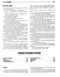
 Next
Next
rn STEERING II 41 ing gear in this condition operates as a typical recir culating ball type manual steering gear Hydraulic Al fluid is bypassed through the valve so that it does not restrict manual operation Rasskvom ensssuns nrscmmuu Ann urrnmmi Slle o mus nerainmc s 5 2 J T Z e All models use a recirculating ball type power steer THR 3 6 l CAVITV ing gear Steel balls act as a rolling thread between SHAW pur sm N the steering gear wormshaft and the rack piston nut SEAL HOUSING Wormshaft fore and aft thrust is controlled by a SHAFT WWF thrust bearing and two races at the lower end and a 4 I N NG bearing assembly in the adjuster plug at the upper 5 END end The lower thrust bearing races are conical and l PLAYE provide continual spring loaded pressure on the worm VANE I SEALS shaft to prevent loss of thrust bearing preload The L adjuster plug provides initial preload adjustment when ngsgnvom 2 servicing the gear HOLE As the wormshaft is turned right the rack piston SPRING m j E moves upward turning the wormshaft left moves the PRESSURE rack piston downward RELIEF pgggsugg UNION The rack piston teeth mesh with the sector which is VALVE now AND FILTER forged as part of the pitman shaft Turning the worm TR l FIu E SSEMBLv shaft turns the pitman shaft which through mechani VALVE EXIT ORIFICE cal linkage turns the wheels HQLE AJ 2 so F II 67 Puwur SI rInp Pump Pump The Vgngtypg 0ng an digp acgmgn pump deve consequently the valve body tend to resist any turn ops the system oil pressure that is applied against the ins ffoI that is 8PPll d As Toslstolloo to t I I I K by rack piston nut to rotate the pitman shaft fig 1 67 the wheels and valve body increases the torsion bar The integral pump reservoir provides a reserve sup ds ls t II Il l E hs sill sllflfi fo Iolsto Wgh n 2 ply of Oiifor the hydmuiic System va ve o y ince t e spoo va ve is connecte o e The reservoir cap is vented tomaintain atmospheric stub shaft by 3 loc3tllI8 Pm tho spool Volvo also pressure in the reservoir and to allow air trapped in Fozstss glI Vs s lJ JolY As tho sgooldvolzs the system tg ggcapg ro a es e ui iree ions passages mac me in o A flow control valve contained within the pump is the spool Vs lV are brought lllto allgllmsllt Wltll used to control and maintain system operating pres II I lIlIIlI I8 Dsssagos in tho VI 1lV body WlI these sure A pressure relief valve is incorporated into the Posssgos sI aligned lIlElI PI sssIlI s fluid from ills flow control valve The flow control valve can be ser DUIIIP is dlfssiod T hI oIiEl I tho aligned Dsssslos and viced without removing the pump from the engine against either side ef the r cI I t Hydraulic Assist vmumz umn rnwen mrnmu The power steering gear has an open center three A variable ratio power steering gear is included in way rotary valve to control hydraulic assist Pump the optional power steering package offered on supplied oil is applied to the pressure hole in the gear Cherokee Wagoneer and Truck models CJ 5 and CJ 7 housing and then routed by the valve through the gear models are equipped with a constant ratio steering oil passages fig 11 68 and 11 69 gear Through mechanical connections the valve body The ratio of a steering system is the relationship of spool valve torsion bar and stub shaft which is pin steering wheel movement to that of the front wheels ned to the torsion bar are in effect attached to the in terms of the number of degrees that the steering front wheels Due to the pressure exerted on the front wheel must be moved to turn the front wheels one wheels by the weight of the vehicle the wheels and degree