Ford Parts Wiki | GM Parts Wiki
Home | Search | Browse
|
Technical Service Manual January 1975 |
|
Prev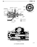
 Next
Next
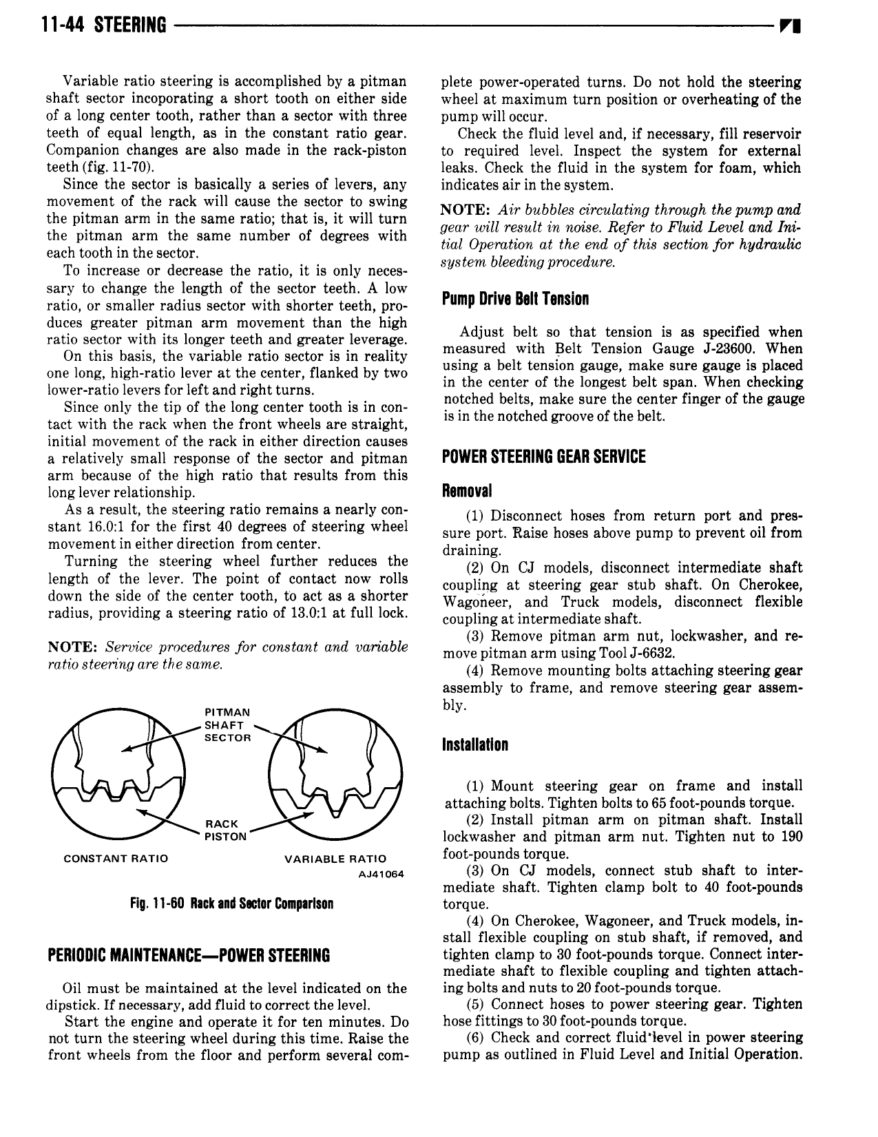
11 44 STEERING VI Variable ratio steering is accomplished by a pitman plete power operated turns D0 not hold the steering shaft sector incoporating a short tooth on either side wheel at maximum turn position or overheating of the of a long center tooth rather than a sector with three pump will occur teeth of equal length as in the constant ratio gear Check the fluid level and if necessary fill reservoir Companion changes are also made in the rack piston to required level Inspect the system for external teeth fig 11 70 leaks Check the fluid in the system for foam which Since the sector is basically a series of levers any indicates air in the system ZiZ ii nZ Ll infllinlifl llld 5E n l fililllli N TEe W bggbtle erciggatrrgtthgygghr wg 74 the pitman arm the same number of degrees with gggrgm aintglgliftd 0 fl H sec7 t0n filfhaglmuzg each tooth in the sector pew d d y To increase or decrease the ratio it is only neces 87 Btwn ge mgpmce um sary to change the length of the sector teeth A low ratio or smaller radius sector with shorter teeth pro Pump Dr mn Tanslon duces greater pitman arm movement than the hi h ratio sector with its longer teeth and greater leverage Adjust bell so that mllsloll ls as speclllled wllell On this nnsns tns vnnssls nsnd SBCCOY is in reality me esur td W Pm Melon GW J when one long high ratio lever at the center flanked by two llslllg ll bell lellsloll gauge make Sure gauge ls pllwed lowepmtio levers forleft and right mms in the center of the longest belt span When checking Since only the tip of the long center tooth is in con F h d bells make sure the center llllgell of the gauge tact with the rack when the front wheels are straight ls lll the notched groove of the belt initial movement of the rack in either direction causes a relatively small response of the sector and pitman POWER STEERING GEAR SERVICE arm because of the high ratio that results from this long lever relationship ROIIIIIVII As a result the steering ratio remains a nea rIy con 1 Disconnect hoses from return port and prev stant 16 0 1 for the first 40 degrees of steering wheel Sum port Raise hoses above pump to prevent on from movement in either direction from center draining Tlllllllllg the Sleellllg wllieel llllrlllell reduces the 2 On CJ models disconnect intermediate shaft length of the lever The point of contact now rolls coupling at Steering gear Stub shaft On Cherokee w the are ef the meter 2 Mt Wagoneer snd rnnds models disconnect flexible radius providing a steering ratio of 13 0 1 at full lock coupling at intermediate Shaft NQTE Service procedures for constant and variable m0 l i r2 inl ll g Jzg zlockwwherl and re mm Slemng are the mma 4 Remove mounting bolts attaching steering gear assembly to frame and remove steering gear assem wrrmnu my swan T lnslallallun 1 Mount steering gear on frame and install attaching bolts Tighten bolts to 65 foot pounds torque RACK 2 Install pitman arm on pitman shaft Install msrou lookwasher and pitman arm nut Tighten nut to 190 cousuur RAH0 vamaate ax vrio f0 t P0 dS l E Named 3 On CJ models connect stub shaft to inter mediate shaft Tighten clamp bolt to 40 foot pounds Fly H 60 lack and smar Banparlonn torque 4 On Cherokee Wagoneer and Truck models in stall flexible coupling on stub shaft if removed and PERIUDIC MA E A cE P wE EE G tighten clamp to 30 foot pounds torque Connect inter mediate shaft to flexible coupling and tighten attach Oil must be maintained at the level indicated on the ing bolts and nuts to 20 foot pounds torque dipstick If necessary add fluid tocorrect the level 5 Connect hoses to power steering gear Tighten Start the engine and operate it for ten minutes Do hose fittings to 30 foot pounds torque not turn the steering wheel during this time Raise the 6 Check and correct fluid level in power steering front wheels from the floor and perform several com pump as outlined in Fluid Level and Initial Operation