Ford Parts Wiki | GM Parts Wiki
Home | Search | Browse
|
Technical Service Manual January 1975 |
|
Prev
 Next
Next
142748
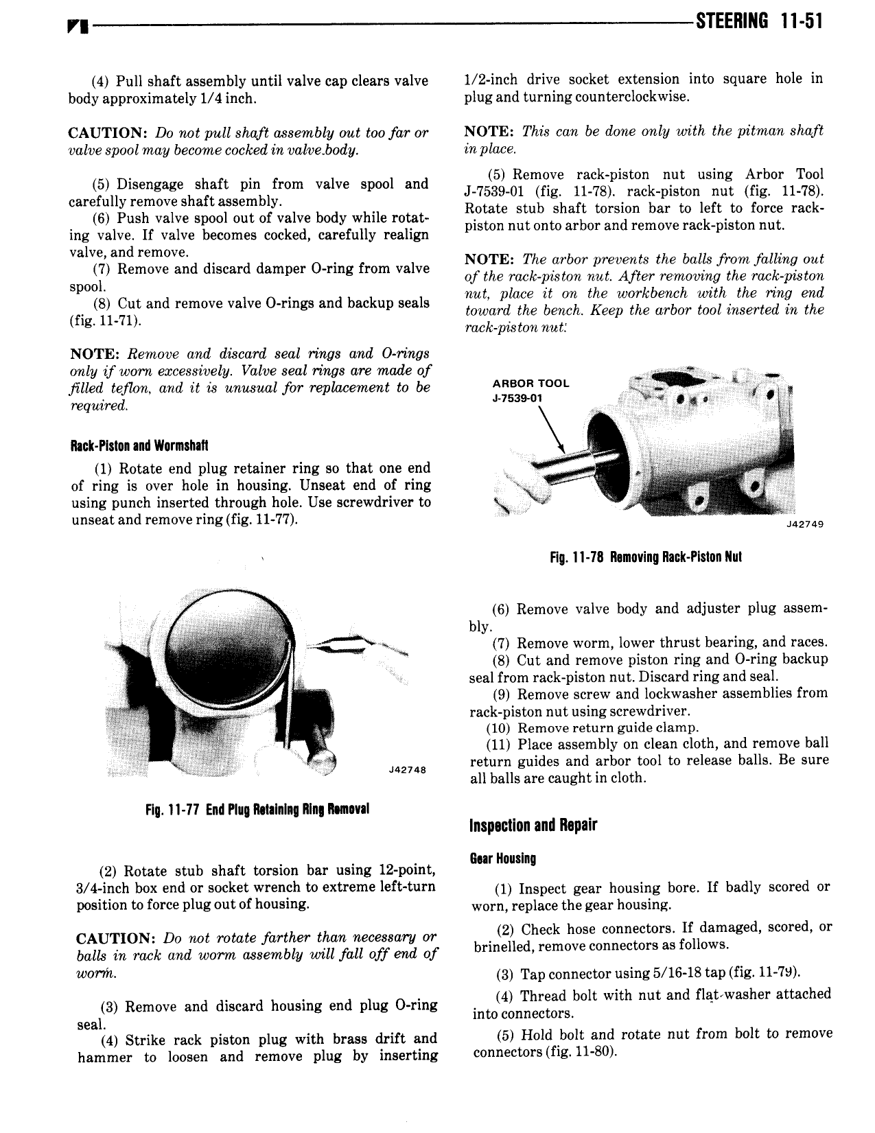
r STEEI1Il 6 11 51 4 Pull shaft assembly until valve cap clears valve 1 2 inch drive socket extension into square hole in body approximately 1 4 inch plug and turning counterclockwise CAUTION Do not pull shaft assembly out too far or NOTE This can be dcme only with the pitman shaft valve spool may became cocked in valvebody in place 5 Disengage shaft pin from valve spool and J 7g en2gv 71g3pis k l 0nusLl 1i b r11 l carefully remove Sh ftass mbly Rotate stub ghaft torsion b r to left to Rice rack 6 Push We W M 0 vm body me me piston nu onto arbor an remove mk ttm nut ing valve If valve becomes cocked carefully realign p valve and remove 7 Remove and discard damper O ring from valve N E The arbor prevents the balk from fallmq out Spool of F e Zacck pzston A ftirg rerrzomnghtlzel raclt pasta nu pezon ewor enourt emngen fig a t and remove Valve 0 rmgs and backup seals toward the bench Keep the arbor tool inserted in the rack pals ton nut NOTE Remove and discard seal rings and O rings only tf worn excessively Valve seal rings are made of V 3 39 QV jilled teflon and it is unusual for replacement to be A T I EXy required 53 j fg i Rack PI 1u ndlIl rmsIntI V g 5g 1 Rotate end plug retainer ring so that one end xv V gis t 4 of ring is over hole in housing Unseat end of ring V using punch inserted through hole Use screwdriver to unseat and remove ring fig 11 77 i L2749 Hg II 18 lkmavinq Rack Plslnn Nut It 3 bl 6 Remove valve body and adjuster plug assem V W V t t Ai i iE Y w 7 Remove worm lower thrust bearing Aand races y V 8 Cut and remove ptston ring and O ring backup i 6 seal from rack piston nut Discard ring and seal W R 9 Remove screw and lockwasher assemblies from fj V rack piston nut using screwdriver 3 5 10 Remove return guide clamp 5 i r i Ai 11 Place assembly on clean cloth and remove ball M Tcfct V I 142748 return guides and arbor tool to release balls Be sure X all balls are caught in cloth Flu 1I 77 End Plug Rmlnlnii 1 In Ilunml lnspminn and Repair Bn II I 2 Rotate stub shaft torsion bar using 12 point r Ws nu 3 4 inch box end or socket wrench to extreme left turn 1 Inspect gear housing bore lf biidiy stm ed gr l l i0 W force PWS out of h z worn replace the gear housing CAUTION Do me rotate farther thhh hetetshn M b Q1 gllgavrgiaged scored or balLs in rack and worm assembly will fall off end of w h 3 Tap connector using 5 16 18 tap fig 11 7 3 Remove and discard housing end plug 0 ring inm n gSb lt mth nut and flqtlwasher attached l seam Strike rack piston plug with bi ass drift and 5 Hold Abolt and rotate nut from bolt to remove hammer to loosen and remove plug by inserting 0 V 5 fil U 8O