Ford Parts Wiki | GM Parts Wiki
Home | Search | Browse | Marketplace | Messages | FAQ | Guest
|
Technical Service Manual January 1975 |
|
Prev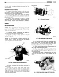
 Next
Next
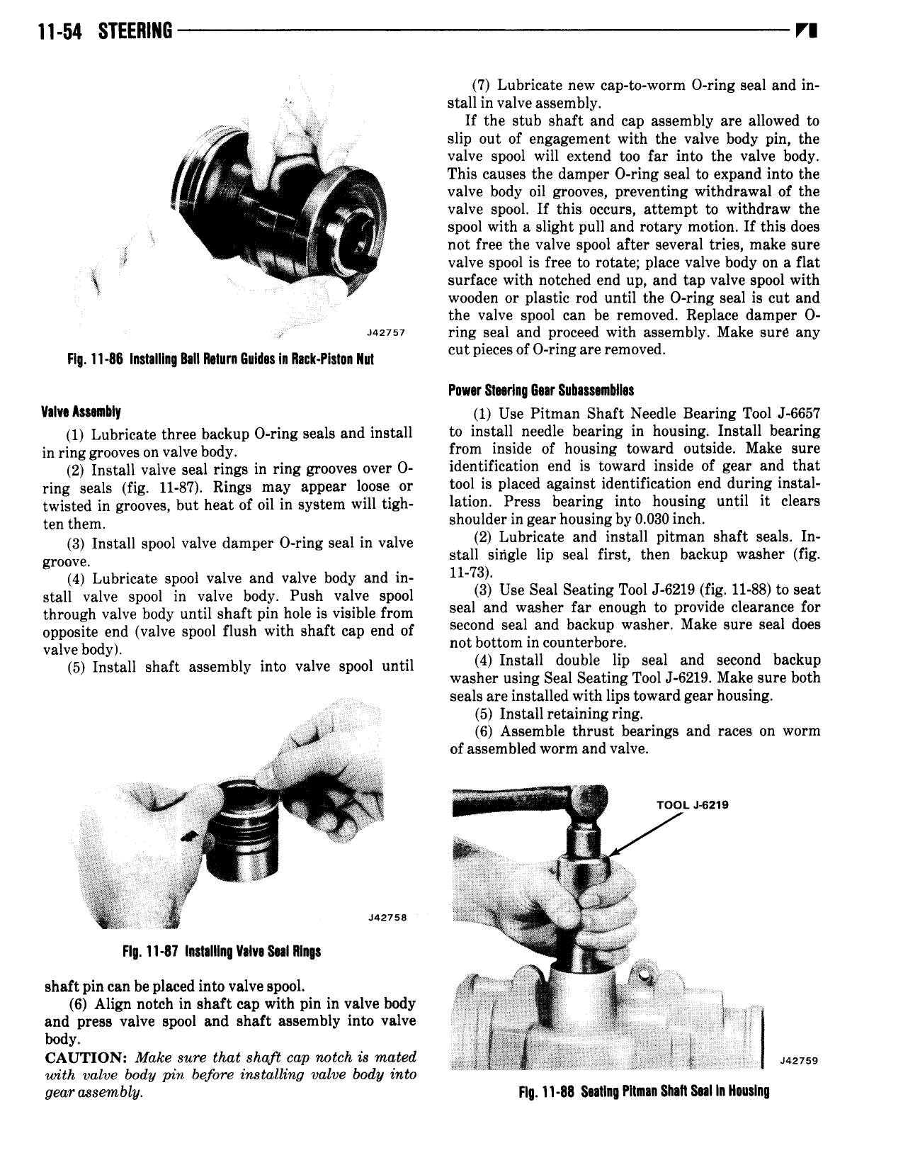
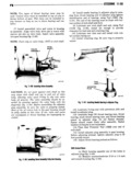
ll 54 STEERING VI 7 Lubricate new cap to worm O ring seal and in stall in valve assembly W 1 If the stub shaft and cap assembly are allowed to I slip out of engagement with the valve body pin the I j valve spool will extend too far into the valve body i 1 This causes the damper 0 ring seal to expand into the in valve body oil grooves preventing withdrawal of the ar 9 valve spool If this occurs attempt to withdraw the spool with a slight pull and rotary motion If this does v not free the valve spool after several tries make sure I rl g j valve spool is free to rotate place valve body on a flat XI L surface with notched end up and tap valve spool with wooden or plastic rod until the 0 ring seal is out and the valve spool can be removed Replace damper O uzvsv ring seal and proceed with assembly Make sure any Fl IHS lnslalllng Ball Mum Guida In Ilan Plslun llul cut pieces of Ofmg are rem v d Pow Staring Gear Suhasanuln Vim IWWMY 1 Use Pitman Shaft Needle Bearing Tool J 6657 1 Lubricate three backup 0 ring seals and install tu install needle bearing in housing Install bearing in ring grooves on valve body from inside of housing toward outside Make sure 2 Install valve seal rings in ring grooves over 0 identification end is toward inside of gear and that ring seals fig 11 87 Rings may appear loose or Wal is placed against identification end during instal twisted in grooves but heat of oil in system will tigh lation Brees bearing into housing until it clears ten them shoulder in gear housing by 0 030 inch I II I I d O I I 2 Lubricate and install pitman shaft seals In gmgg nsw gpm Va ve amper Img Sea In va ve stall single lip seal first then backup washer fig 41 o ll ri 1 bod uw 73 MII Q8I3 Brl gISl 0 v Bb I y v h vallvgnspllgl 3 Use Seal Seating Tool J 6219 fig 11 88 to seat through valve body until shaft pin hole is visible from Seal and Wiashgf garkvnuughhto plqmlde clearanfedfor opposite end valve spool flush with shaft cap end of S Sea an ac p was su Sea V y El 3 i tLl l T I i d I I II I III I I I t I ns ou e up sea an secon ac up 5 Install S a t assem y In 0 V8 ve gpm lm I washer using Seal Seating Tool J 6219 Make sure both I seals are installed with lips toward gear housing Ir 5 Install retaining ring 6 Assemble thrust bearings and races on worm Im I A I of assembled worm and valve I t like Q all s a s m g al I Y e TOOLJ 62 9 V at at to V Et e l W t I 5 1 3 4 g f wg I V 2 iixfi falim FI ll 07 lnmlllnq ll lv S lll n a 7 shsftpincan be plscedinto valvespool S Q 6 Align notch in shaft cap with pin in valve body g I g I ll and press valve spool and shaft assembly into valve 3 2 Q I gf I Y l L L CAUTION Make sure that shq if edp notch is mated 5 Iii qgg ggifi fig I It 275 with valve body pin before installing valve body into W W gear assembly Hq 11 B8 Smlng Flinn Shall Sal In Ilwslnu