Ford Parts Wiki | GM Parts Wiki
Home | Search | Browse | Marketplace | Messages | FAQ | Guest
|
Technical Service Manual January 1975 |
|
Prev
 Next
Next
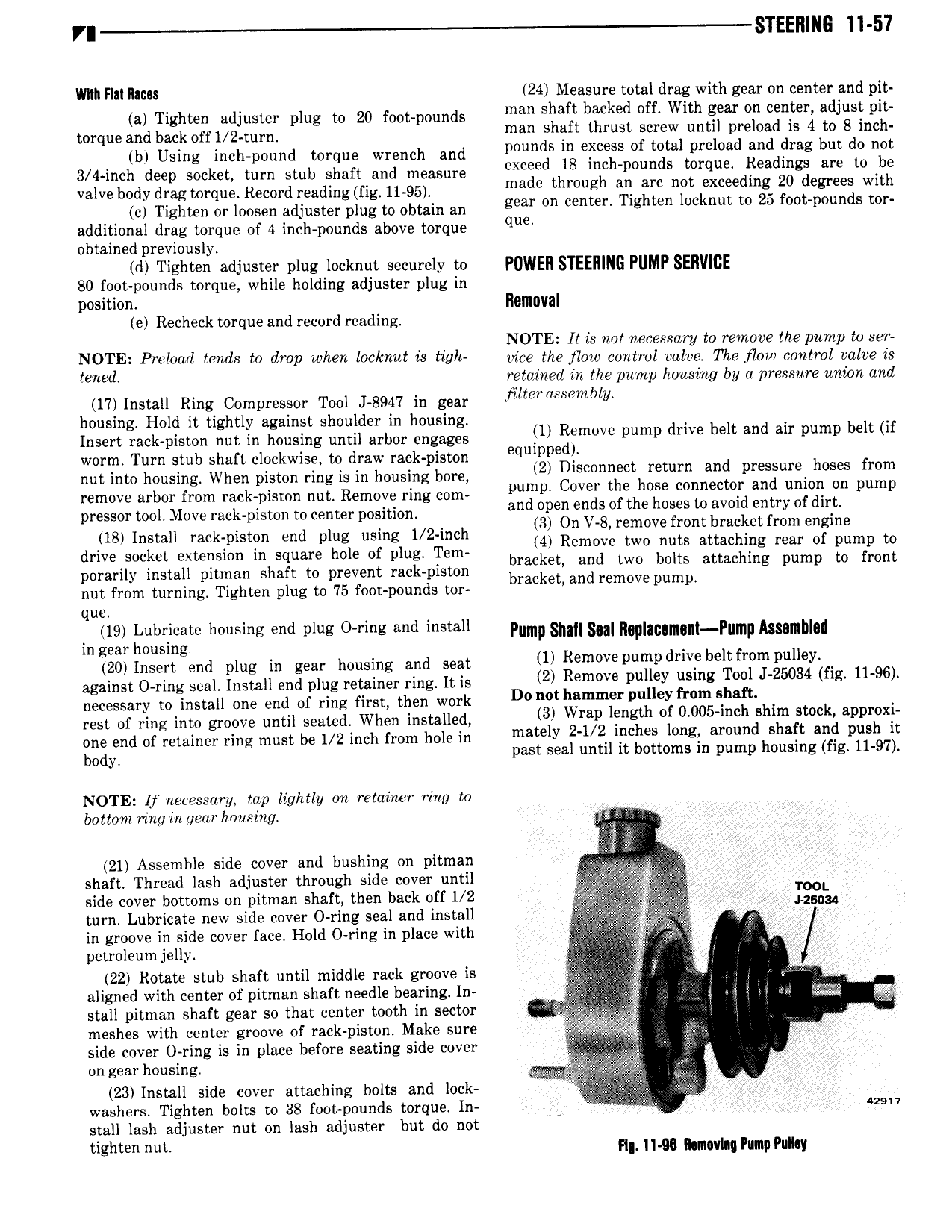
VI STEEl1 I i 11 57 Wilt Flnl Rm 24 Measure total drag with gear on center and pit ta Tighten adjuster nlug tu 20 teuunnunds man shaft backed off With gear on center adjust pit torque and back OTH 2 tunn man shaft thrust screw until preload is 4 to 8 inch b Using inch pound torque wrench and P0 d5 m SS of total preload and drag but do not 3 Mneh deen Socket turn etuh Shaft and measure exceed 18 inch pounds torque lteadlngs are to be vnlvehudy uh ugtnnnne Reeund nendtngmut u 95 e made through an arc not exceeding 20 degrees with et Tighten en loosen adjuster nlug eo Obtain an gear on center Tighten locknut to 25 foot pounds tor additional drag torque of 4 inch pounds above torque q obtained previously d Tighten adjuster plug locknut securely to POWER STEERING PUMP SERVIBE 80 foot pounds torque while holding adjuster plug in DOSition RGIIIIIVBI e Recheck torque and record reading NOTE It is nn necessary to remove the pump to ser IIIOEE Prehzad tends to drop when locknut is ttgh mice the flow control valve The flour control valve is we retained in the pump housing by a pressure union and 17 Install Ring Compressor Tool J 8947 in gear Hlt gSembly housing Hold it tightly against shoulder in housing t Insert rack piston nut in housing until arbor engages lll Remus pump drlve belt and all pump belt ll worm Turn stub shaft clockwise to draw rack piston Bqulppegl nut into housing When piston ring is in housing bum 2 lswnuect return and pressuree hoses from remove arbor from rack piston nut Remove ring com pump Cover the hose connector and umorl lm pump pressor tool Move rack piston to center position and lyeg l l f the lwies lz SW entity l llllilh 18 Install rsck piston end plug using 1 2 inch Mt RZm vgrigvlgviuignaetgiitit xglrelgglnim m drive socket extension in square hole of plug Tem b k g p ll rac et and two bolts attaching pump to front porarily install pitman shaft to prevent rack piston bracket and remove u nut from turning Tighten plug to 75 foot pounds tor p mp que in tgt kgsgjgte s rrd pus and t l Pump slun sun nuuutuun ramp imutuu 20l Insert end plug in gear housing and son 1 Remove pump drive belt from pulley I against O ring seal Install end plug retainer ring It is 2 Remove P ll Y usmg T l J 25034 HE H 96 necessary to install one end of ring first than work D0 Mt lwmrner pulley from ehaft u t rest of ring into groove until seated When installed 3 Wm lswth of 0 O05 m l slum S k 8Pl X one end of retainer ring must be 1 2 inch from hole in mately l itlltcgeit longg aroundhshaft 339 Pilslgq body pas sea un 1 1 o oms in pump ousmg ig NOTE If necessary tap lightly on retainer ring to bottom ring in year housing 21 Assemble side cover and bushing on pitman ue e shaft Thread lash adjuster through side cover until Q side cover bottoms on pitman shaft then back off 1 2 V 12 turn Lubricate new side cover O ring seal and install in groove in side cover face Hold O ring in place with 0 petroleum jelly 22 Rotate stub shaft until middle rack groove is V f t aligned with center of pitman shaft needle bearing In I ii 4 3 gg stall pitman shaft gear so that center tooth in sector Q e te 1 W meshes with center groove of rack piston Make sure r Z 2 o gn V side cover O ring is in place before seating side cover 4 i on gear housing tu 23 Install side cover attaching bolts and lock I washers Tighten bolts to 38 foot pounds torque In r new stall lash adjuster nut on lash adjuster but do not tighten wt H 11 llunavlng Pump Pulhy