Ford Parts Wiki | GM Parts Wiki
Home | Search | Browse | Marketplace | Messages | FAQ | Guest
|
Technical Service Manual January 1975 |
|
Prev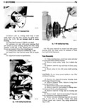
 Next
Next
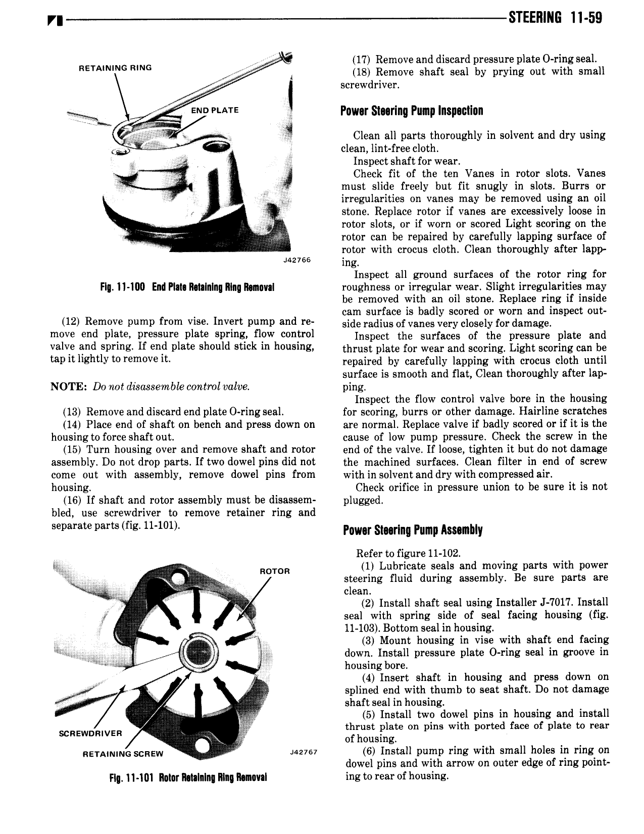
y STEERING ll 59 z 17 Remove and discard pressure plate O ring seal nsmnumc RING I ig Remove shaft seal by prying out with Smell screwdriver l V MTE Pnwor Slnrlng Pump Inspaullnn Clean all parts thoroughly in solvent and dry using I 6 clean lint free cloth Oi iii Inspect shaft for wear r Check fit of the ten Vanes in rotor slots Vanes must slide freely but fit snugly in slots Burrs or Yi irregularities on vanes may be removed using an oil stone Replace rotor if vsnes are excessively loose in f rotor slots or if worn or scored Light scoring on the V rotor can be repaired by carefully lapping surface of rotor with crocus cloth Clean thoroughly after lapp Jazvee ingl Inspect all ground surfaces of the rotor ring for F Il W Elll PIII lltttlnlnp lllllq Iltmuvll roughness or irregular wear Slight irregularities may be removed with an oil stone Replace ring if inside cam surface is badly scored or worn and inspect out 12 Remvve Pump from vise lm P mP and l side radius of vanes very closely for damage m0V end Pli l P 5 F Plate P l Ylf W fl l Inspect the surfaces of the pressure plate and valve and spring If end plate should stick in housing eh ust plate for wear and scoring Light scoring can be t llltl Eh lY r m V l repaired by carefully lapping with crocus cloth until surface is smooth and flat Clean thoroughly after lap NOTE Do not disaasemble control valve ping Inspect the flow control valve bore in the housing 13 Remove and discard end plate 0 ring seal for scoring burrs or other damage Hairline scratches 14 Place end of shaft on bench and press down on are normal Replace valve if badly scored or if itAis the housing to force shaft out cause of low pump pressure Check the screw in the 15 Turn housing over and remove shaft and rotor end of the valve If loose tighten it but do not damage assembly Do not drop parts If two dowel pins did not the machined surfaces Clean filter in end of screw come out with assembly remove dowel pins from within solventanddry with compressedair housing Check orifice in pressure union to be sure it is not 16 lf shaft and rotor assembly must be disassem plugged bled use screwdriver to remove retainer ring and l l mg u 1 1l Pnwor Slnrlnu Pump Asnmbly Refer to figure 11 102 l Roma 1 Lubricate seals and moving parts with power l Q steering fluid during assembly Be sure parts are e l clean i l p A 2 Install shaft seal using Installer J 7017 Install y seal with spring side of seal facing housing fig i 11 103 Bottom seal in housing 3 3 Mount housing in vise with shaft end facing l xs i p W i down Install pressure plate O ring seal in groove in housing bore v 4 Insert shaft in housing and press down on J A splined end with thumb to seat shaft Do not damage shaft seal in housing v y 5 Install two dowel pins in housing and install SCREWDRIVER lt thrust plate on pins with ported face of plate to rear of housing RE MNING SCREW uzvsv 6 Install pump ring with small holes in ring on dowel pins and with arrow on outer edge of ring point Flq ll lDl Mlllf lI 1IIlIII MII lllllvll ing to rear of housin8