Ford Parts Wiki | GM Parts Wiki
Home | Search | Browse | Marketplace | Messages | FAQ | Guest
|
Technical Service Manual January 1975 |
|
Prev
 Next
Next
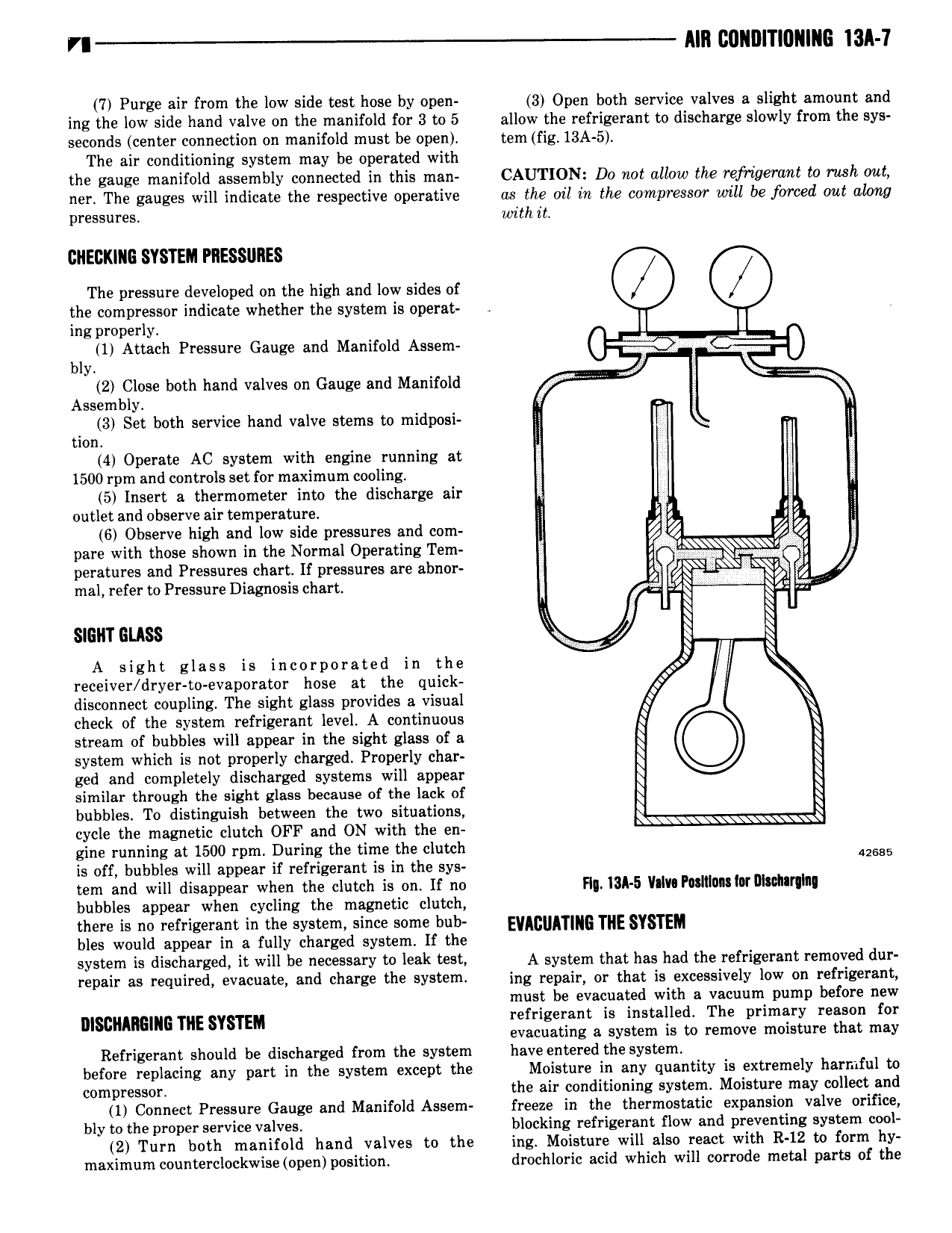
MII GUIIIIITIGIIIIIG ISA 7 7 Purge air from the low side test hose by open 3 Open both service valves a slight amount and ing the low side hand valve on the manifold for 3 to 5 allow the refrigerant to discharge slowly from the sys seconds center connection on manifold must be open tem fig 13A 5 The air conditioning system may be operated with the gauge manifold assembly connected in this man CAUTION Do not allow the refrigerant to rash out ner The gauges will indicate the respective operative as the oil in the compressor will be forced out along pressures with it GIIEGKIIIG SYSTEM PIIESSIIIIES The pressure developed on the high and low sides of Q 0 the compressor indicate whether the system is operat ing properly I I 1 Attach Pressure Gauge and Manifold Assem 6 bly 2 Close both hand valves on Gauge and Manifold K Assembly 3 Set both service hand valve stems to midposi tion ll 4 Operate AC system with engine running at 1500 rpm and controls set for maximum cooling 5 Insert a thermometer into the discharge air i outlet and observe air temperature 1 E 2 6 Observe high and low side pressures and com Q Z Q pare with those shown in the Normal Operating Tem g jl peratures and Pressures chart If pressures are abnor J mal refer to Pressure Diagnosis chart R N Q SIGHT GLASS A sight glass is incorporated in the receiver dryer to evaporator hose at the quick disconnect coupling The sight glass provides a visual f check of the system refrigerant level A continuous stream of bubbles will appear in the sight glass of a S Q system which is not properly charged Properly char Q Q ged and completely discharged systems will appear Q Q similar through the sight glass because of the lack of Q Q bubbles To distinguish between the two situations Q E cycle the magnetic clutch OFF and ON with the en gine running at 1500 rpm During the time the clutch 42685 is off bubbles will appear if refrigerant is in the sys tem and will disappear when the clutch is on lf no Fl I3I 5 Vllll PIISIIIUISIM Dl dI I II bubbles appear when cycling the magnetic clutch there is no refrigerant in the system since some hub EyA q Y M bles would appear in a fully charged system If the system is discharged it will be necessary te leak test A system that has had the refrigerant removed dur repair 85 required V3 1 Snd charge the SYS l fl ing repair or that is excessively low on refrigerant must be evacuated with a vacuum pump before new mscnnmnm TNE SYSTEM refrigerant is iinstallemti The primary realso 1 for evacuating a sys em is remove mois ure a may Refrigerant should be discharged from the system have entered the system before replacing any part in the system except the Moisture in any quantity is extremely harmful to compressor the air conditioning system Moisture may collect and 1 Connect Pressure Gauge and Manifold Assem freeze in the thermostatic expansion valve orifice bly to the proper service valves blocking refrigerant flow and preventing system cool 2 Turn both manifold hand valves to the ing Moisture will also react with R 12 to form hy maximum counterclockwise open position drochloric acid which will corrode metal parts of the