Ford Parts Wiki | GM Parts Wiki
Home | Search | Browse | Marketplace | Messages | FAQ | Guest
|
Technical Service Manual January 1975 |
|
Prev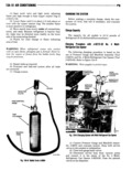
 Next
Next
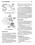
VI AIR ZUIIIIITIGNIIIG l3Il ll 4 Attach the necessary number of refrigerant 1 Discharge and evacuate System cans to the dispenseri Refer to Charge Capacity for 2 With an control valves on the charging station the proper weight of refrigerant necessary to charge closed open the refrigerant drum valve the vehicle helllg 5el Vl ed 3 Bleed the charging cylinder through valve 5l Opell Oh dispenser Peieeek valve l 0 5eh the located on the back of the control panel directly above eehiel service hose at the Pl e5 lll e Gauge and cylinder Close bleed valve occasionally to check level Mahlleld Set allewlhg refrigerant W Plll Ee air fem in charging cylinder Raising the refrigerant drum the line Tighten the service hose connection and close ehcve the level cf the chen ging cylinder will gneed up lllepelleel Defeeek V8l le the filling process When correct amount of 6 Open the Sllctleh lehlhpllllhdl gauge hahd valve refrigerant is in the charging cylinder close the bleed and one dispenser petcock valve Do not open the dis Valve charge high pressure gauge hand valve 4 Close refrigerant drum valve 7 Start engine and place AC controls in the 5 cinse low pressure control valve 1 and mid h leXll m ellellhg Deelileht The 0mPl eee0l Wlll 0Pe position cracked suction and discharge service valves rate and help pull refrigerant gas into the suction side 5 Fully Open refrigerant cnnlml valve 4 end ofthe system high pressure control valve 2 Liquid refrigerant con nornt mt n t tgrrnn t rmt may be parte npagtt tt greed lll cherries eyhheler will ehler h eh ehle el eve hmtw Hum 12 F to Speed up the 7 When full charge has entered system close refrigerant control valve 4 and high pressure control 3 when the lng i eii igeirgnt can ig ei np y Open valve 2 Back seat the suction and discharge service another dispenser petcock valve to continue charging Vhlllee the system 9 Continue charging until the specified amount NOTE Dllrllly ehllrglllyt Pl l e tlflltl lll fmlll Qf lll or refrigerant it an the system The frost line on the relrfcle to peas air over the condenser which will refrigerant can will indicate what portion of the lll lFll the lltlle eQl lTetlfll Chll 9l7l9 refrigerant in the can has entered the system This Check may he used eg e visual guide when A System 8 Disconnect service hoses from suction and dis requires a fraction of a full can charge service valves 9 Operate system 10 to 15 minutes to allow it to N0TE Ul lll l F llmlP l l is available weigh the normalize and to determine if the system will cycle r 4rr1 emut cans before and dzmrg the charging pro properly r cn zn c to aware that the correct amount of rqrriyerrnzt rs bvmg used 10 When system is fully charged close the suction cumpnssun eh e ll wee hehe Valve and all elsheheer vet The tnmprtsnnr is the ttit rinntn twttynnntn k ValV9S reciprocating type lt is attached to the enmne with a lll B l e el the setlleh ehe lleeheree seem mounting mntktt ts shown m ngnrts nano and 11 valves for their normal operating position by turning them fully counterclockwise 12 Loosen the Pressure Gauge and Manifold Set COIIl II 0 SIII Vllvt Clif DIIQIIGSIS service hoses to allow refrigerant trapped in hoses to dlgcheirgei The compressor should be at operating temperature 13 Remove Pressure Gauge and Manifold Set and to Pel f l l all ecellmie lies installalldustcaps on fittings 1 Install Pressure Gauge and Manifold Assem 14 Operate the system 10 to 15 minutes to allow it bly Tool 23575 to normalize and to determine if the system will cycle 2 Fl 0 f Seh the Sl letleh and discharge el Vlee nrcpeirly valves by turning them clockwise 3 Discharge refrigerant remaining in compressor clllflllll PI IMdIII 0 Vlllll J 23500 Pllfilllll Alf DMI by opening suction gauge hand valve slowly l Mr M y Slglllm 4 Open the suction gauge hand valve and close the high pressure gauge hand valve 5 Start engine and operate compressor Pressure The following charging procedure is based on the wm build up muiulu Scuu cumuressui at 150 cu 200 use of the Portable Air Conditioning Service Station pounds uressurg TO J 23500 6 Pressure should hold if the discharge valve is operating properly Loss of pressure indicates leaking WARNING Wear goggles to protect eyes compressor discharge valve or bead gasket