Ford Parts Wiki | GM Parts Wiki
Home | Search | Browse | Marketplace | Messages | FAQ | Guest
|
Technical Service Manual January 1975 |
|
Prev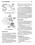
 Next
Next
lllll GDIIDITIUIIIIIG I3A I3 8 Remove battery ground cable from lower 1 Discharge remaining refrigerant in system bracket to compressor attaching stud then back seatl both service valves to prevent air 9 Remove upper bracket to intake manifold moisture and dirt from entering system attaching bolt 2 Remove belts 10 Remove lower bracket to engine attaching 3 Remove clutch pulley and woodruff key from bolts nuts and washers compressor shaft 11 Remove compressor and mounting bracket as 4 Remove seal plate capscrews and washers pry an assembly and place on work bench seal plate loose and remove V V 12 Remove bracket and bracket attaching studs 5 Carefully pry behind seal drive ring that part of the seal assembly farthest back on the shaft and c0IIIpI SS II ll l llIll0Il V remove seal assembly l 1 Bench assemble the lower mounting bracket to 6 Clean new Seal assembly c ml mS ln l a the cOmpl ESs0l refrigeration oil 2 P t cl bracket assembly on engllll alfglllgglllllrgllzgfllgghzpsland mlm NOTE lleanlinesst careful handling and clean 3 Install upper bl acket tO l takE manifold refrlzgerlztion oil are important elements of success ill attaclllllg bolt sea rep ucement 4 Install battery ground cable to lower bracket Vll P ll l lll less Carbon llllllg ll loose to compressor stud us seg assem y 5 Install coll to upper c0mpl Bss0r t0 manlg0ld over compressor shaft with carbon ring retainer facing bl acketV out Move assembly in and out on shaft to seat 6 IllStall8ltel l lat l neoprene ring on shaft Push assembly in until seal 7 Install compressor drive belt set and adjust to retainer assembly contacts bearing race If carbon ring propel tgllsloll was loose position it in ring retainer with polished 8 Attach compressor service valves and lines ld l P f d l t eS 9 urge Compressor 0 mr an Open sewwe va NOTE The carbon ring mustseatin the retainer 10 Connectclutch Wim 8 C t t faces of compressor and seal ll t bl V oa ma mg sur V l l l 11 Connect angry nega we ca E plate with a film of refrigeration oil Position seal ring l plate cnllwnsm Fr sul pl nl in groove on the seal plate and install sea l 9 Install seal plate capscrews and tighten evenly The compressor front seal is serviced in kit form Wlllle F0t l lg ll lPF S 0l ll ll Center Seal Plat on kit components oro shown in figure 13A 12 All seal shaft by lightly tapping plate Tighten cavwswa in 8 parts must be replaced if a leak has been detected at llaK0 lP lt l 090l ll P lS l l the seal Back Plata 0 lIln Seal lla Immnl NOTE A small amount of oil around the shaft seal w 0 P normal and does rmt indicate a seal leak All seal parts NOTE On gikpeylinder engines it is not necessary to were dipped in oil at the time of assembly and opera remove hg ggmprgggnr tion may force out surplus oil 1 Isolate and remove compressor l 2 Remove four back plate attaching screws using l oiccuscx Torx BitTooIJ 25359 l l ell t fl ll5 llNG 3 Remove back plate by gently prying it loose from crankcase Pry in such a manner to pull parallel mom seal QE l lV to bearing surface lr ae is l l Vl l ASSEVBLV 4 Remove O ringseal from back plate iop 5 Clean back plate and apply a light film of ff ll EUG l refrigeration oil to 0 ring sealing area 5 UE 6 nl ll l 6 Position O ring seal on back plate and install l lU back plate over rear bearing and into the crankcase Z 7 Install four back plate attaching screws using P iQ Torx Bit Tool J 25359 and tighten in a diagonal pat 0rr0M i tern to 9 to 17 foot pounds torque ilslkgkir gl Auisoo 8 Install and purge compressor of air 9 Leak test system Evacuate and charge if Fl 13A 12 Danprnmr Saltonpmau ani mlm S rv4