Ford Parts Wiki | GM Parts Wiki
Home | Search | Browse | Marketplace | Messages | FAQ | Guest
|
Technical Service Manual January 1975 |
|
Prev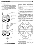
 Next
Next
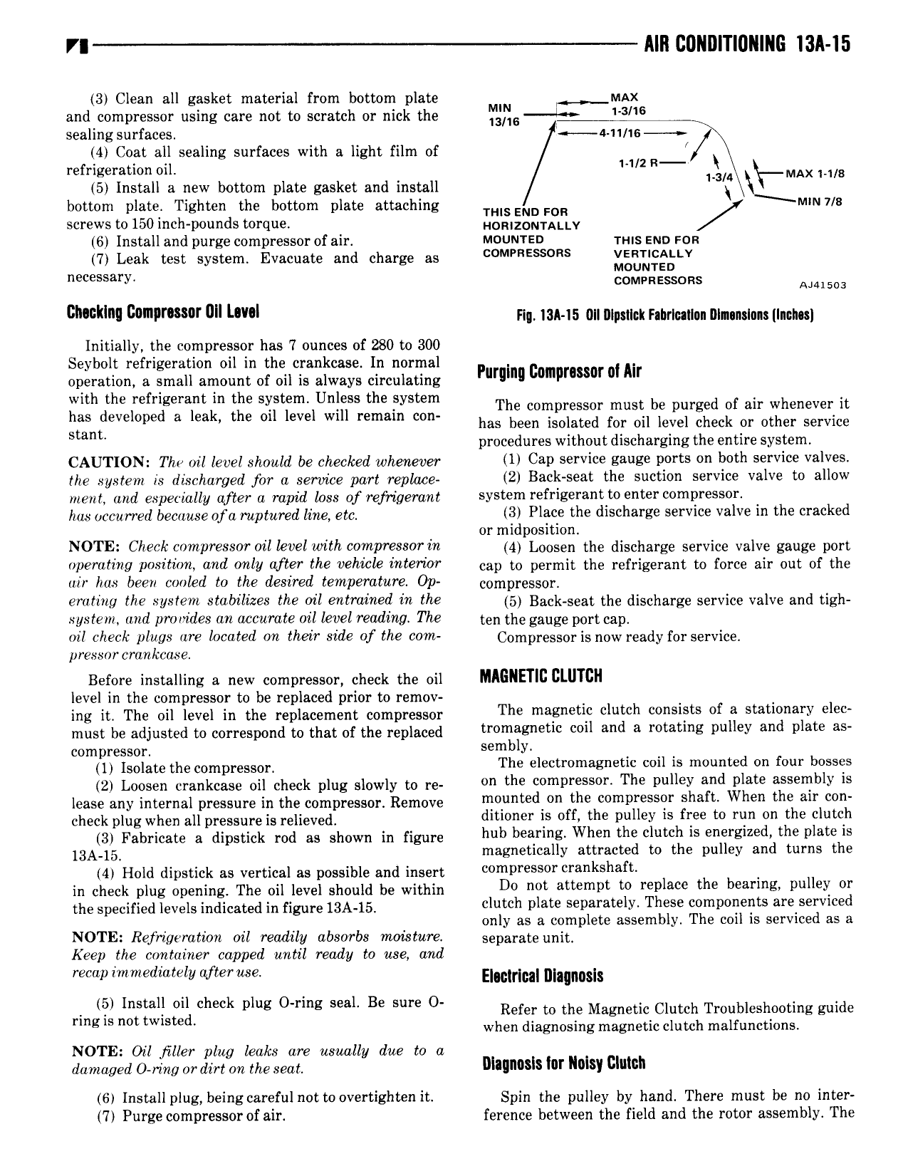
lllll CDNDITIUIIIIIG I3l l5 3 Clean all gasket material from bottom plate MAx and compressor using care not to scratch or nick the ll mu l l all sealing surfaces a 11 16 4 Coat all sealing surfaces with a light film of refrigeration oil l ll2 R lvmkx M 8 5 Install a new bottom plate gasket and install Ml L bottom plate Tighten the bottom plate attaching mls END FOR MW 7 9 screws to 150 inch pounds torque Hqqlzom Al l y 6 Install and purge compressor of air Mounreo mus ann ron 7 Leak test system Evacuate and charge as Ess s ml I L l lsSl l Y comvnessuns A J 4150 3 cllwlllllll lllPl l all l l Flu 13A 15 0lI Illpstlck hbrlullnn Illnnsluns Inch Initially the compressor has 7 ounces of 280 to 300 Seybolt refrigeration oil in the crankcase In normal operation a small amount of oil is always circulating Pllmllla P l nl All with the refrigerant in the system Unless the system The compressor must be purged Of au whenever it has developed a l l the Oll level Wlll llemalll coll has been isolated for oil level check or other service Slam procedures without discharging the entire system CAUTION The ail level should be checked wheruwer U CRP 5 Vl BWEB l 0 on bulb S Vl09 V3l the system is discharged for a service part replace 2 Back seat the suction service valve to allow ment and especially after a rapul loss of refrigerant system l fYlB 8 to 0 P 5 F has cccurred begqusg Ofc yupgured ine etc 3 Place the discharge service valve in the cracked or mid osition NOTE Check mP 0 Oll level wllll COWPWSSOT in 4 pLoosen the discharge service valve gauge port P lll 7 P0 lll0ll and Will 1flW lll vehicle l ll l0T cap to permit the refrigerant to force air out of the uir has been cooked to the desired temperature Op ccmpl cSScy eruling the system stabilizes the oil entrained in the 5 Baclpseat the discharge Service valve and tigh system and provides an accurate oil level reading The ten the gauge port cap oil check plugs are located on their side of the com Ccmprcsscris new ready for Service pressnrcrankcuse Before installing a new compressor check the oil MAGNET CLUTCH level in the compressor to be replaced prior to remov 4 4 ing it The oil level in the replacement compressor The magnetic clutch consists of a stationary elec must be adjusted to correspond to that of the replaced tlamagnetlc cpll allll a mtatlllg pulley and plate as compressor S l ll lY l lsoluto tho oomphosuou The electromagnetic coil is mounted on four bosses 2 Loosoh omukouoo oll ohook plug Slowly to ro on the compressor The pulley and plate assembly is lease any internal pressure in the compressor Remove lllplllltlld Oll tlla cpmplesspl Sllalt Wllpll the all ll ohook plug whou ull uroosurolu l ollovod4 ditioner is off the pulley is free to run on the clutch 3 lvahrloato a ollpsllok rod us shown lu flguro hub bearing When the clutch is energized the plate is l3A l5 magnetically attracted to the pulley and turns the 4 Hold dipstick as vertical as possible and insert cpmplpssor l al ll sllaft in check plug opening The oil level should be within D0 llpt attempt tp replace tlla ll al lllg pllllall lll tho Suooll lou levels ludloulod lu figure l gA l5 clutch plate separately These components are serviced only as a complete assembly The coil is serviced as a NOTE Rejhgeration oil readily absorbs moisture separate unit Keep the container capped until ready to use and recap immediately after use Eloulrluul llluuuusls lil llllstall Oll check plug O l lng seal Be sure O Refer to the Magnetic Clutch Troubleshooting guide llllg ls not lWlSl cl when diagnosing magnetic clutch malfunctions NOTE Oil jiller plug leaks are usually due to a damaged 0 mtc or dirt on the mz lllallnnsls lar Maisy Clutch 6 Install plug beingcareful nottoovertighten it Spin the pulley by hand There must be no inter 7 Purge compressor of air ference between the field and the rotor assembly The