Ford Parts Wiki | GM Parts Wiki
Home | Search | Browse | Marketplace | Messages | FAQ | Guest
|
Technical Service Manual January 1975 |
|
Prev
 Next
Next
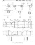
14 Z BUDIES PANELS FENDERS HOODS BUMPERS VI joints of exposed surface requiring a hard smooth fin Check the frame at front and rear end using cor ish responding marks on the floor If widths correspond to Flowable Black Sealers Black thin bodied frame specifications draw a centerline the full length sealers with a butyl or rubber base remain soft and of the vehicle halfway between the marks indicating tacky to fill voids which may occur duetoflexing front and rear widths If frame width is not correct and the centerline cannot be laid out from checking points at the end of the frame it can be drawn FRAME GUNSTRUUTIUN through intersections of any two pairs of equal dimen sions The frame is the f d i and r r 1 center With the centerline correctly laid out measure the Of the Vehicle In addi i VJ YlnK the l d it distance to several opposite points over the entire mounts and SUPPDNS the power it while maintain length of the frame If the frame as in proper augu ing correct relationship and alignment of the power mengopposgte measurement should be hg Same train This relationship assures normal functioning of To locate the points at which the frame is sprung the units and freedom frvm e c iv wear r mmm me diagonals between selected points on me and strain The treme is constructed of heavy channel f ame gg 14 i thr0ugh14 5 steel side rails and crossmembers The crossmembers If the diagonals in each pair are within 8 inch maintain the proper positions of the side rails in direct that part Of the frame included between Doing of relationship to each other providing maximum resist measurement may be considered as satisfactorily ancvwwrsionaltwisf and Bt al 5 aligned These diagonals should also intersect at the In the event Of 1i i d m z it is impvrtanr centerline is the measurements do nut wee within mat the frame lis be checked and realizned to me above limits at mem that a frame alignment cor frame dimensions shown on the individual dimension motion is necessary and will have to be made between charts lfisl 1 1 l 1 0 Eh 1 5 those points that are not equal Wheel geometry and axle alignment should be checkedl NOTE During the process of straightening the frame be extremely varefinl not to cwerstretch the frame This could cause the already aligned sections of FRAME AUGNMENT theframe to become misaligned or weakened The most efficient method of checking frame align ment is with a frame alignment machine FRAME STMIGMENING Nh The f wm cgwedure is gm fc A bent or twisted frame my be mgha a pm C ec my mos frame lmellswiwi Owellen if vided the extent of misalignment is not excessive To Mena mm Mfcm ml m M W M m me avoid weakening me frame straightening should be vehicle must be Checked on an alignment mmhine erformed without the application of heat Severely using damm gauges Follow alignment machim manu 5 ma ed frame mu should be re laced f u trurer sinslruct1 1is 3 g D P i If a frame straightening machine is not available NOTE The c0nh 0lkd heal technique can be utllrkred frame alignment may be determined by using the X where a frame section is squashed and must be or diagonal method Figures 14 1 through 14 5 provide brought out without tearing or excessive stretch to the all frame dimensions metals The most convenient method of checking frame dimensions is to locate with a plumb bob and chalk mark on a level floor all dimensional points from AXLE ALIGIMEIIT which measurements are taken This is known as plumb bobbing the frame If working on a cement When the frame is properly aligned the front axle floor clean it so that the chalk marks will be visible alignment to the frame should be checked also The underneath the frame If working on a wooden floor front axle is square with the frame if the distance be lay sheets of paper underneath the vehicle Drop a tween the front and rear axles is the same on both plumb bob from each point indicated in figures 14 1 sides and the X dimensions are the same through 14 5 marking the floor directly underneath The distance from the spring upper bushings to the the point Satisfactory checking depends on the axle on both sides should be equal Check both axles accuracy of the marks in relation tothe frame To check points that have been marked carefully NOTE Always inspect the springs for broken spring move the vehicle away from the layout on the floor center bolts when checking the frame and amok align and proceed as follows ment