Ford Parts Wiki | GM Parts Wiki
Home | Search | Browse | Marketplace | Messages | FAQ | Guest
|
Technical Service Manual January 1975 |
|
Prev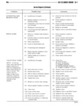
 Next
Next
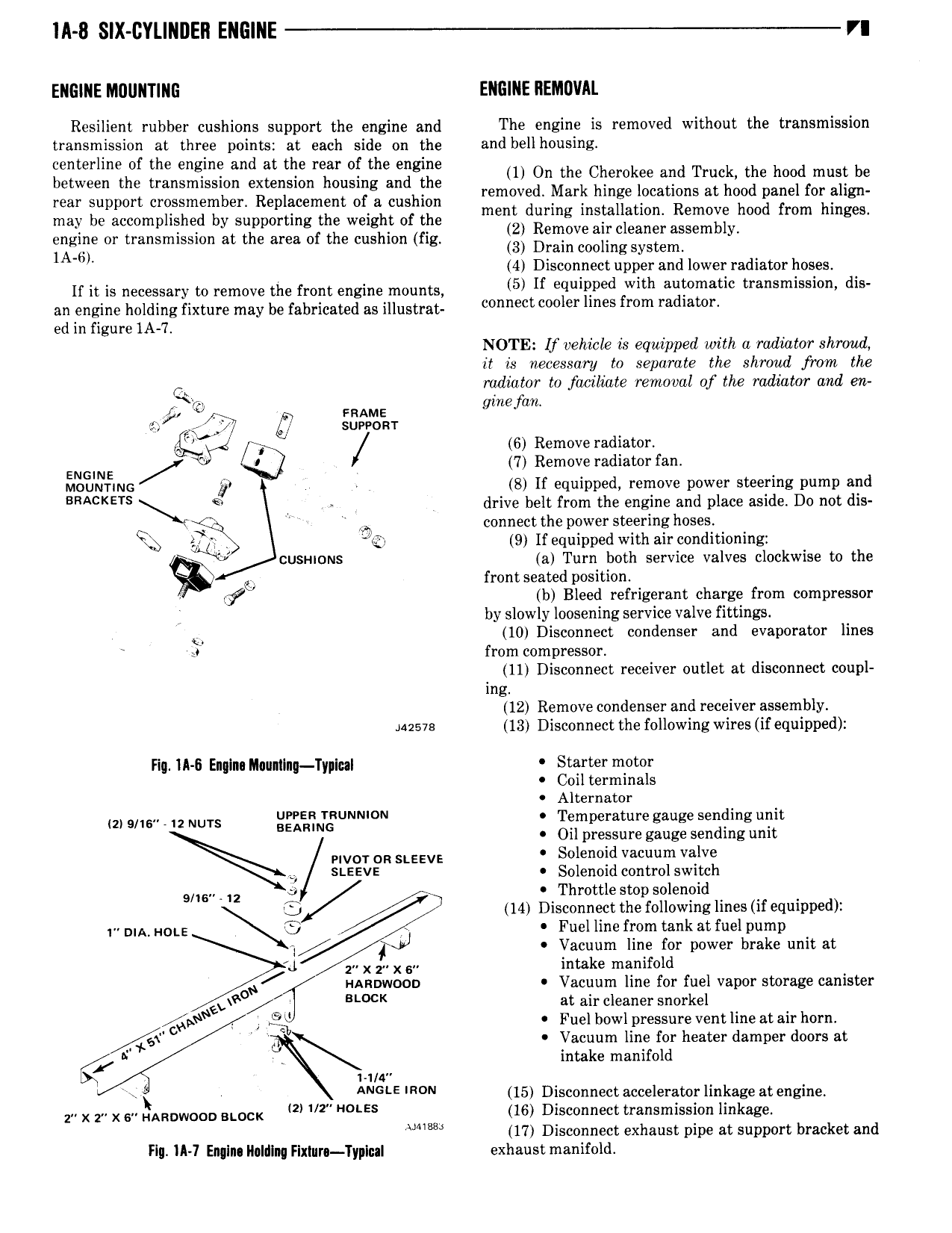
IA 8 SIX CYL NDEN ENGINE VI ENGINE MOUNTING ENGINE IIEMDVAL Resilient rubber cushions support the engine and The engine is removed without the transmission transmission at three points at each side on the and bell housing centerline of the engine and at the rear of the en ne between the transmission extension housing andgthe ll On the Cllemllee alilll Tmclg the hood mllsll be rear support eeeeeeeemeee Replacement er e cushion mMd Mark hm r r at md v 1 mav be accomplished by Supporting the Weight of the ment during installation Remove hood from hinges engine or transmission at the area of the cushion fig lzl Remove all cleaner assembly 1A 6T 3 Drain cooling system 4 Disconnect upper and lower radiator hoses If it is necessary to remove the front engine mounts 5 If squiqved with tl a Sm l dis an engine holding fixture may be fabricated as illustrat Connect l r lmes mm ad al l ed in figure IA 7 NOTE Lf vehicle is equipped with a radiator shroud it is necessary to separate the shroud from the O radiator to faciliate removal of thee radiator and ea Q gmefart sf 47 3 e 6 Remove radiator ENGTNE 7 Remove radiator fan Moummc gt e 8 If equipped remove power steering pump and BRACKETS Q drive belt from the engine and place aside Do not dis Y l Tx connect the power steering hoses JQ 9 If equipped with air conditioning cusi nous a Turn both service valves clockwise to the g E front seated position sig b Bleed refrigerant charge from oompressor by slowly loosening service valve fittings L 10 Disconnect condenser and evaporator lines J from compressor 11 Disconnect receiver outlet at disconnect coupl mg 12 Remove condenser and receiver assembly suave 13 Disconnect the following wires if equipped Hq IA 6 Englna Mou 1Inq TypluI Starter motor Coil terminals Alternator 1 6 2 NUTS g E TN UNN 0 Temperature gauge sending unit Oil pressure gauge sending umt PIVOT OR SLEEVE Solenoid vacuum valve ei SLEEVE Solenoid control switch 9 6 2 E Throttle stop solenoid G c 14 Disconnect the following lines if equipped ms HOL Fuel line from tank at fuel pump E lvl Vacuum line for power brake unit at L 2 X 1 X 6 intake manifold mxnnwooo Vacuum line for fuel vapor storage canister LLW 0 at air cleaner snorkel Qty Fuel bowl pressure vent line at air horn O Vacuum line for heater damper doors at Q N intake manifold e 1 1 a ANGLE 0 15 Disconnect accelerator linkage at engine ze X Ee X EH HARDWOOD BLOCK 2 V2 E5 16 Disconnect transmission linkage 17 Disconnect exhaust pipe at support bracket and Flu IA 7 Englns Iluldlnq Fixtur Typlnal exhaust manifold