Ford Parts Wiki | GM Parts Wiki
Home | Search | Browse | Marketplace | Messages | FAQ | Guest
|
Technical Service Manual January 1975 |
|
Prev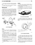
 Next
Next
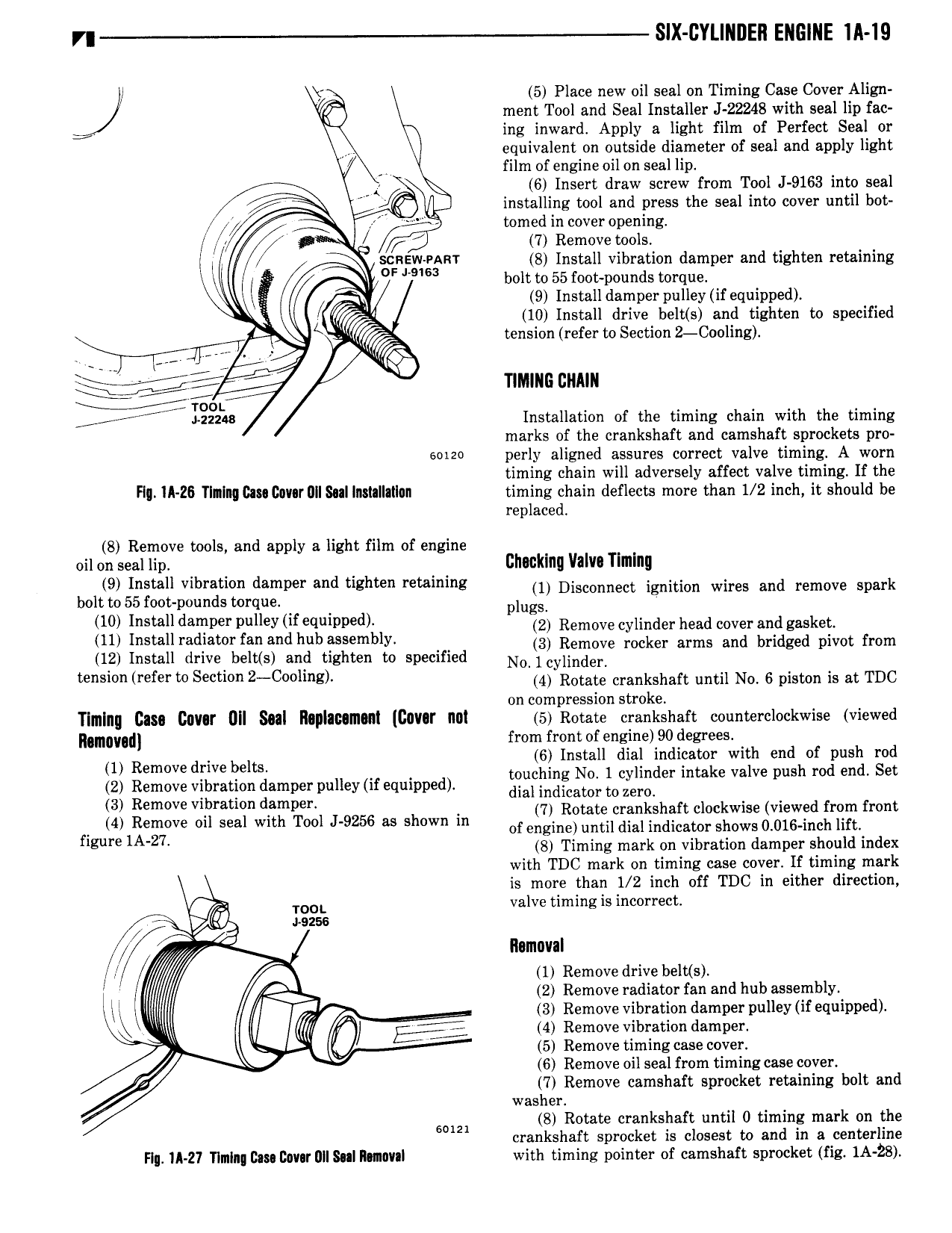
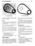
SIX CYLINDER ENGINE lll 19 5 Place new oil seal on Timing Case Cover Align J ment Tool and Seal Installer J 22248 with seal lip fac ing inward Apply a light film of Perfect Seal or V equivalent on outside diameter of seal and apply light film of engine oil on seal lip 6 Insert draw screw from Tool J 9163 into seal K installing tool and press the seal into cover until bot y tomed in cover opening V i p 7 Remove tools zinfgggev b l Install vibraition damper and tighten retaining 0 t to 55 foot poun s torque x 9 Install damperpulley ifequipped I 10 Install drive belt s and tighten to specified fr 5 S tension refer to Section 2 Co ling roor Q to TINIINE DNAIN lggzlha Installation of the timing chain with the timing marks of the crankshaft and camshaft sprockets pro soizo perly aligned assures correct valve timing A worn timing chain will adversely affect valve timing If the FI IA 26 Tlnlnq Gm Cover IIII Sul lnmllailan timing chain deflects more than 1 2 inch it should be replaced 8 Remove tools and apply a light film of engine oil on seal lip clllflkllll Vlllll Tllllllly 9 Install Vlbllatlml damper and llgllml reulllllllg 1 Disconnect ignition wires and remove spark bolt to 55 foot pounds torque plum 10 lllstall dalllper pulley lf eqlllllpelll 2 Remove cylinder head cover and gasket lll l llred 3 r lan and llllll B ml ly 3 Remove rocker arms and bridged pivot from IQ Install dr1ve4belt s and tighten to specified N0 1cylind r r f S 2 C l on Rotate crankshaft ootii Ne o piston is at me on compression stroke Timing Casa Dnv r 0lI Seal llapI c m al llavar nal 5 Rotate crankshaft oonnterolookwiee viewed Rgmgygdl from front of engsine 90 degrees 1 Remove drive belts 6 Install dial indicator with end of push rod touching No 1 cylinder intake valve push rod end Set 2 Remove vibration damper pulley if equipped dial indicator to mm 3 Remove vlpmnon d mper 7 Rotate crankshaft clockwise viewed from front 4 Remove 0 ml with M 9256 w of engine e to oai indicator shows o oio neh ne flgmle lA 27 8 Timing mark on vibration damper should index with TDC mark on timing case cover If timing mark is more than I 2 inch off TDC in either direction qs TOOL valve timing is incorrect VG aezss Ilamnval 0 1 Remove drive belt s 2 Remove radiator fan and hub assembly ll i f r J 3 Remove vibration damper pulley if equipped u Ei 4 4 Remove vibration damper 5 Remove timing case cover 6 Remove oil seal from timing case cover 7 Remove camshaft sprocket retaining bolt and washer Som 8 Rotate crankshaft until 0 timing mark on the crankshaft sprocket is closest to and in a centerline Flu IA 2 I Tlmln Bam B0vIrIlIl lIN 1n0V l with timing pointer of camshaft sprocket fig 1A 28