Ford Parts Wiki | GM Parts Wiki
Home | Search | Browse | Marketplace | Messages | FAQ | Guest
|
Technical Service Manual January 1975 |
|
Prev
 Next
Next
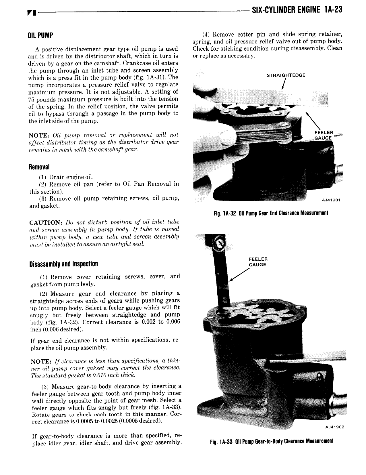
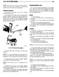
r SIX CYLINDER ENGINE lA 23 Ull PUMP 4 Remove cotter pin and slide spring retainer spring and oil pressure relief valve out of pump body A positive displacement gear type oil pump is used Check for sticking condition during disassembly Clean and is driven by the distributor shaft which in turn is or replace as necessary driven by a gear on the camshaft Crankcase oil enters the pump through an inlet tube and screen assembly j which is a press fit in the pump body fig 1A 31 The sTRA GHTEDGE pump incorporates a pressure relief valve to regulate maximum pressure It is not adjustable A setting of Ajg 75 pounds maximum pressure is built into the tension V hk i of the spring In the relief position the valve permits V Q y V oil to bypass through a passage in the pump body to gan A the inlet side of the pump i QL NOTE Oil pump removal or replacement will not ljE FEE E we z aisznbiizilr timing as me atgmzmmr drive gw cf l A remains in mesh with the camshaft gear J gnu s Ilamuval il rr 1 Drain engine oil 2 Remove oil pan refer to Oil Pan Removal in n this section 3 Remove oil pump retaining screws oil pump AJM901 and gasket Hg IA 32 Dil Pump Gm End Dlnrancu Musurnmsm CAUTION Do rmt disturb position of oil inlet tube and screen ass mbly in pump body If tube is moved within pump body a new tube and screen assembly must be installed to assure an airtight seal 1 Disassembly and Inspection i 1 Remove cover retaining screws cover and gasket from pump body 2 Measure gear end clearance by placing a straightedge across ends of gears while pushing gears up into pump body Select a feeler gauge which will fit P snugly but freely between straightedge and pump 3 body fig 1A 32 Correct clearance is 0 002 to 0 006 V jo 6 inch 0 006 desired 5 lf gear end clearance is not within specifications re place the oil pump assembly W Na NOTE Ifclearance is less than specijicatwns a thin xv if i e ner oil pump cover gakset may correct the clearance The standard gasket is 0 010 inch thick 4 L 3 Measure gear to body clearance by inserting a 7 feeler gauge between gear tooth and pump body inner E wall directly opposite the point of gear mesh Select a as je feeler gauge which fits snugly but freely fig 1A 33 I t Q Y Rotate gears to check each tooth in this manner Cor n at a rect clearance is 0 0005 to 0 0025 0 0005 desired V i Aaaisuz If gear to body clearance is more than specified re place idler gear idler shaft and drive gear assembly Flg lA 33 Ull Pump EIIT 0 ll0dy Dlllrlluu Ihasaramun