Ford Parts Wiki | GM Parts Wiki
Home | Search | Browse | Marketplace | Messages | FAQ | Guest
|
Technical Service Manual January 1975 |
|
Prev
 Next
Next
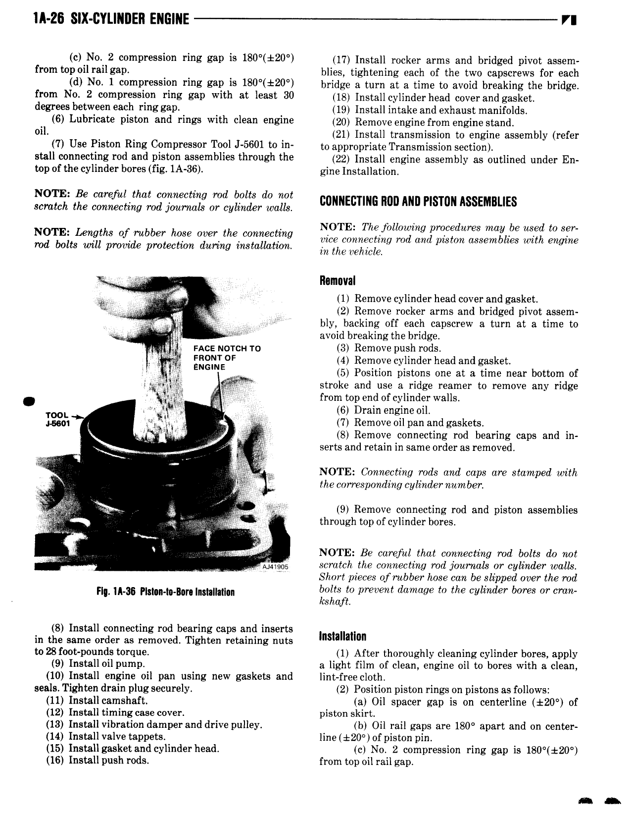
IA 26 SIX CYLINDER ENGINE VI 0 N0 2 0 P 55l0 ring E9D is 180 20 17 Install rocker arms and bridged pivot assem f m WD 0il il86D blies tightening each of the two capscrews for each d Nv 1 compression rms sap is 180 20 bridge a turn at e time to avoid breaking the bridge mm N0 2 00mD j ring E39 With at l 88 30 18 Install cylinder head coverand gasket d 8Y 5 b lZ 98Qh Ting 8811 19 Install intake and exhaust manifolds 6 Lubricate piston and rings with clean engine 20 Remove engine from engine stand 0ll 21 Install transmission to engine assembly refer 7 US i t Ring CPKHPFBSSOF T0 5601 to i to appropriate Transmission section stall connecting rod and piston assemblies through the gg lngiell engine assembly ae engined under En top of the cylinder bores fig 1A 36 gine lngmllatini i NOTE Be care al that connecting md bolts do not scratch the connecting rod joarnals or cylinder walls c EcTI 6 mm Mm Plslmn ASSEMBUES NOTE The following procedures may be used to ser mg of rubber hqse ww me cmmectlng vice connecting rod and piston assemblies with engine ts will proinde protection during installation in the vehicle I We llamuval X 1 Remove cylinder head cover and gasket I 1 2 Remove rocker arms and bridged pivot assem I bly backing off each capscrew a turn at a time to l avoid breaking the bridge V nc uorcu ro 3 Remove push rods l J 0 0F 4 Remove cylinder head and gasket l l G E 5 Position pistons one at a time near bottom of stroke and use a ridge reamer to remove any ridge l i l Lei from top end of cylinder walls J l lw V 6 Drain engine oil 3 2 E i 1 7 Remove oil pan and gaskets L 8 Remove connecting rod bearing caps and in X U r 2 serts and retain in same order as removed NOTE Connecting rods and caps are stamped with the corresponding cylindernumber A A F g 9 Remove connecting rod and piston assemblies is if ef through top of cylinder bores l A NOTE Be carefal that connecting rod bolts do not V Annigee scratch the connecting rod journals or cylinder walls Short pieces of rubber hose can be slipped over the rod l u 36 ylmn Bn mml m bolts to prevent damage to the cylinder bores or cran kshuft 8 Install connecting rod bearing caps and inserts I II I in the same order as removed Tighten retaining nuts ns al on to 28 foot pounds torque 1 After thoroughly cleaning cylinder bores apply 9 Install oil pump a light film of clean engine oil to bores with a clean 10 Install engine oil pan using new gaskets and lint free cloth seals Tighten drain plug securely 2 Position piston rings on pistons as follows 11 Install camshaft a Oil spacer gap is on centerline 120 of 12 Install timing case cover piston skirt 13 Install vibration damper and drive pulley b Oil rail gaps are 180 apart and on center 14 Install valve tappets line t20 of piston pin I5 Installgasketand cylinderhead c No 2 compression ring gap is 180 120 16 Install push rods from top oil rail gap Q L