Ford Parts Wiki | GM Parts Wiki
Home | Search | Browse | Marketplace | Messages | FAQ | Guest
|
Technical Service Manual January 1975 |
|
Prev
 Next
Next
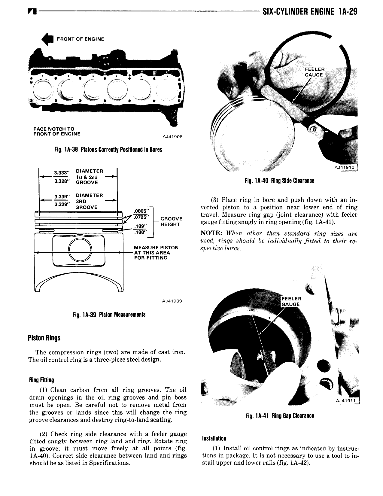
SIX CYLINDEN ENGINE lll 29 room or snows Fasten GAUGE X V j i 1 t ks I qi ii ZJ V M A nc norcu ro 1 V snom or snows MMDB AA al Flu ll 38 Pistons corrmnyrusninqnuaa sqm I n we Amato 1333 A LER t Ja uzu QEOOCE Fig 1A 40 Illng Slda Cluranuu g METER 3 Place ring in bore and push down with an in GROOVE H verted piston to a position near lower end of ring i GROOVE travel Measure ring gap joint clearance with feeler 7 4 9 Hmm gauge fitting snugly in ring npening fig 1A 41 ss NOTE When other than standard ring sizes are used rings should be individauzlly fitted to their re MEASURE PISTGN specticve bores AT mis Anza mn nmnc Amigos i Flq 1A 39 Pislun Mnawrnmls Y Y Y F ii z i Pnstnn Rlngs I The compression rings two are made of cast iron ii The oil control ring is a three piece steel design lo V Q gs Ring Flulng Q 1 Clean carbon from all ring grooves The oil cr drain openings in the oil ring grooves and pin boss Y must be open Be careful not to remove metal from Mami the grooves or lands since this will change the ring Harman mma ummm groove clearances and destroy ring to land seating 2 Check ring side clearance with a feeler gauge fitted snugly between ring land and ring Rotate ring m in groove it must move freely at all points fig 1 Install oil control rings as indicated by instruc 1A 40 Correct side clearance between land and rings tions in package It is not necessary to use a tool to in should be as listed in Specifications stall upper and lower rails fig IA 42