Ford Parts Wiki | GM Parts Wiki
Home | Search | Browse | Marketplace | Messages | FAQ | Guest
|
Technical Service Manual January 1975 |
|
Prev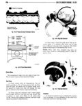
 Next
Next
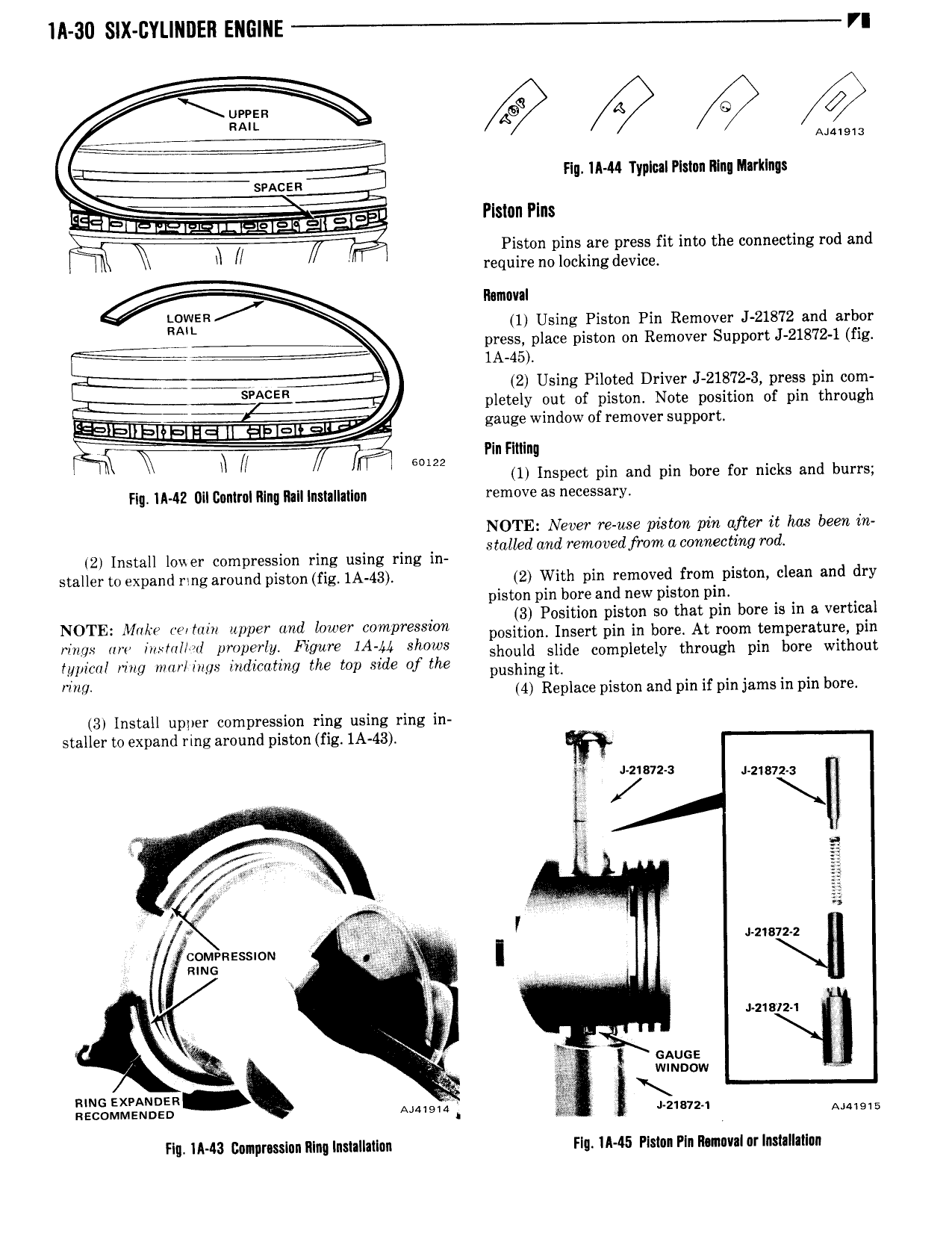
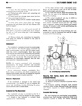
IA 30 SIX CYLINDER ENGINE VI ee it Q e RAIL A Flu IAM Typlul Plstun ltlnu Inrklngs Z rCEIEllL ur4ty 5 giI ET 7l lE2 msn rms E ll z Piston pins are press fit into the connecting rod and l require no locking device r rsrr r lhmnval Qglffn 1 Using Piston Pin Remover J 21872 and arbor 7 press place piston on Remover Support J 21872 1 fig i 1A 45 A ACE 2 Using Piloted Driver J 21872 3 press pin com pletely out of piston Note position of pin through gauge window of remover support N SM2 Ptn Flttlng V V 1 Inspect pin and pm bore for nicks and burrs rtg IMZ ull control lllng Rall lnstallallnn remove as necessary NOTE Never re use piston pin after it has been in stalled and rernooedfrorn a connecting rod 2 Install lovler compression ring using ring in staller to expand ring around piston fig 1A 43 2 With pin removed from piston clean and dry piston pin bore and new piston pin P tht b t l NOTE Make velhlin upper and lower compression possgim Egg gains SSW tp 0n r p2 tJ lg rl mix lm mm I pmpwly Figure IA A Shows should slide completely through pin bore without typical ring mar ings indicating the top side of the pushlngtt Mw 4 Repleee piston and pin if pin jams in pin bore 3 Install upper compression ring using ring in staller to expand ring around piston fig 1A 43 v l pm z J ztsvxu f I 1 S 25 t Ei Y l J 2 872 2 connvnesston I mms c 1 ezwiz 1 L V y anus wmuow L 1 L L mm Flg IA 43 l nnpr sslnn lllng lnstallallnn Flq IA45 Plslnn Pln lI nuv l or lnxtnllatlnn