Ford Parts Wiki | GM Parts Wiki
Home | Search | Browse | Marketplace | Messages | FAQ | Guest
|
Technical Service Manual January 1975 |
|
Prev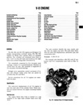
 Next
Next
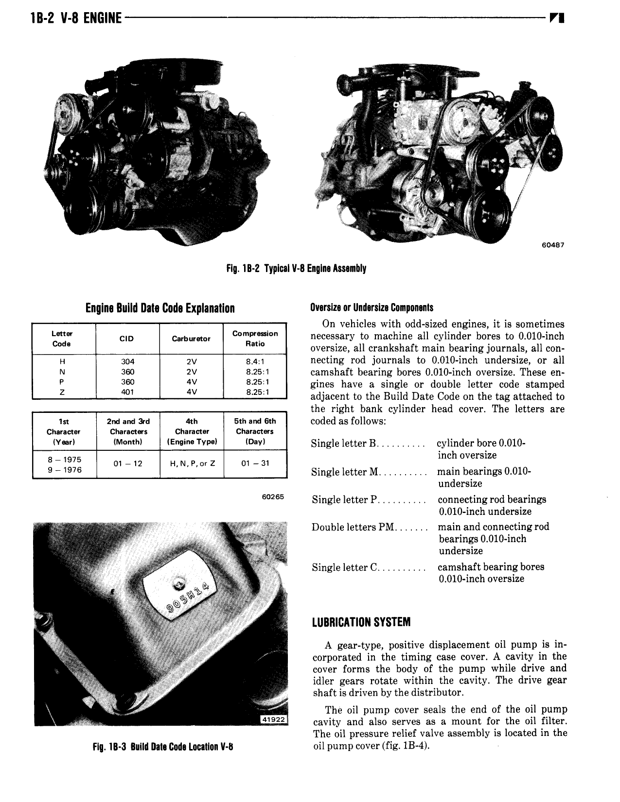
lll 2 V 8 ENGlNE VI Z 5 is s sf a 4 ll 1 k f a 1 i i r so QZ 4 be wig r A A 1 A di it 1 at J cz A W A i Z ill flgi z if Q I t at y iggy f Y 4 ra J1 js r Q 9 1 1 lv v 1 1 I 4 soasv Flq IB Z Typlul V 8 EngIn Ammhly Enqinq Build Daly Gnd Explanation Dv rsIz ur llm rsIz Gampunants On vehicles with odd sized engines it is sometimes cm C P f necessary to machine all cylinder bores to 0 010 inch R oversize all crankshaft main bearing journals all con H 304 gv g 4 1 necting rod journals oo 0 010 inch undersize or all N seo 2V 12 25 1 camshaft bearing bores 0 010 inch oversize These en 360 W 25 gines have a single or double letter code stamped Z 401 4V M5 adjacent to the Build Date Code on the tag attached to the right bank cylinder head cover The letters are in 2 1 me am an sm me sui coded as follows ciuuew commu charm cimmm V l M l lE YYP l DW Single letterB cylinder bore0 010 E 975 O1 12 i 1 i 1 e r z o1 31 mel oversize 9 976 Single letter M main bearings 0 010 undersize 2 5 Single letterP connecting rod bearings 0 010 inch undersize 1 y r j Double letters PM main andconnectingrod y V I g1 a bearings 0 010 inch 5 V undersize t E a X S1ngleletterC camshaft bearing bores a p is V J 0 010 inch oversize l vb 4 aq 0 3 w l Z Y 3 f4 aj 1 z V t 93 Q 4 LUBIIICATIUN SYSTEM fj 2 j Wg T y f f A geaptype positive displacement oil pumpris in T i corporated in the timing case cover A cavity in the J 5 cover forms the body of the pump while drive and 3 ge I idler gears rotate within the cavity The drive gear f shaft is driven by the distributor 1 ll ef 3 The oil pump cover seals the end of the oil pump W EEE cavity and also serves as a mount for the oil filter The oil pressure relief valve assembly is located in the Flq lIl 3 lllll IMI CMO Llwllilln V l oil pump cover fig 1B 4