Ford Parts Wiki | GM Parts Wiki
Home | Search | Browse | Marketplace | Messages | FAQ | Guest
|
Technical Service Manual January 1975 |
|
Prev

 Next
Next
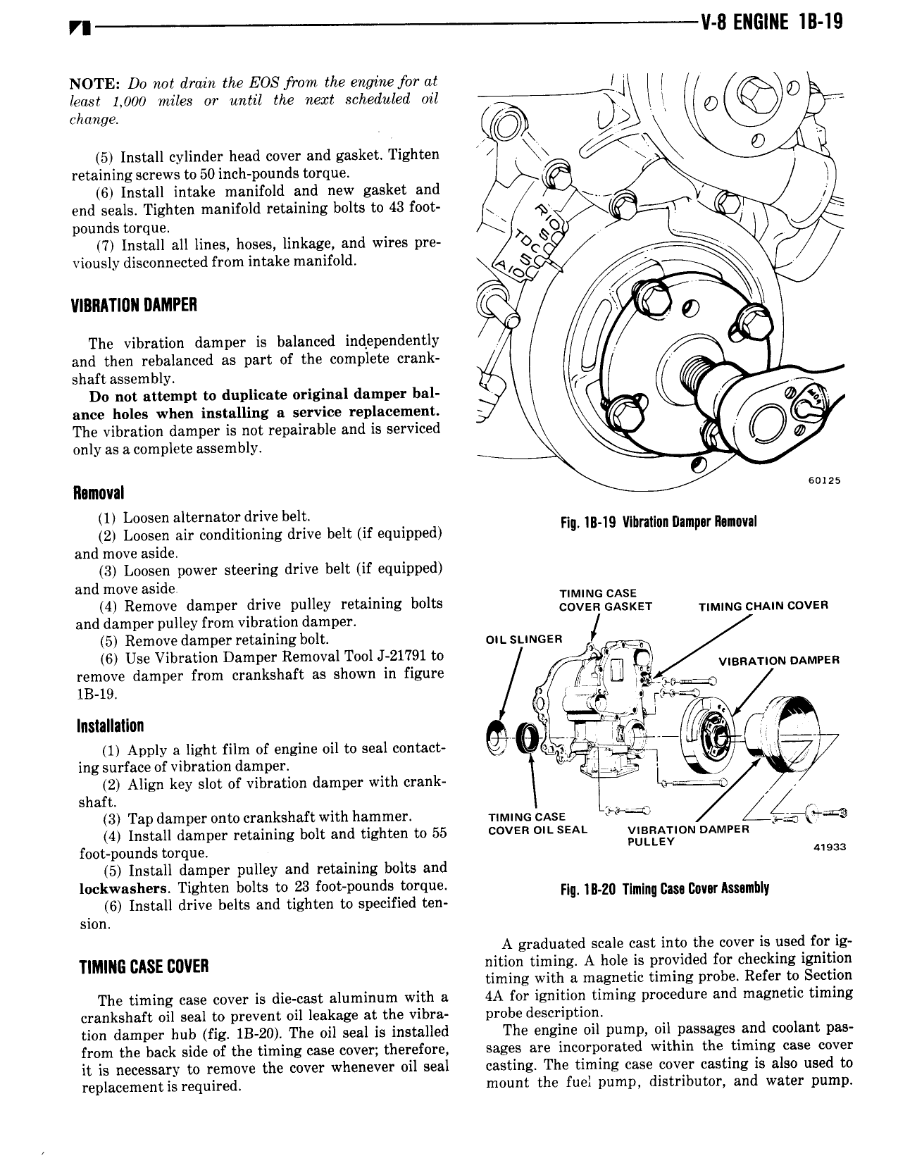
Vl 8 ENGINE IB 19 NOTE Do not drain the EOS from the engine for at I J kms 1 000 miles or until the next scheduled oil G 0 I change Q 5 Install cylinder head cover and gasket Tighten i W O Al retaining screws to 50 inch pounds torque fi 6 Install intake manifold and new gasket and l I end seals Tighten manifold retaining bolts to 43 foot 6 pounds torque 0 7 Install all lines hoses linkage and wires pre oc viously disconnected from intake manifold AI 0 v vmnmun nnmren Q 6 The vibration damper is balanced independently and then rebalanced as part of the complete crank shaft assembly 4 W A Do not attempt to duplicate original damper bal I 0 ance holes when installing a service replacement The vibration damper is not repairable and is serviced X 0 only as a complete assembly O Removal I Loosen alternator drive belt 2 Loosen air conditioning drive belt if equipped FI IB lg vlbmwn nmlm mma and move aside 3 Loosen power steering drive belt if equipped and move aside nmiu casa 4 Remove damper drive pulley retaining bolts COVESGASKET TIMING CHAIN COVER and damper pulley from vibration damper 5 Remove damper retaining bolt OWSUNGER G 6 Use Vibration Damper Removal Tool J 2I l9l to J3 i V VIBRATION DAMPER remove damper from crankshaft as shown in figure L J El r is 19 6 gg Installallun i yild K fri 1 Apply a light film of engine oil to seal contact in if 1 ing surface of vibration damper J 2 Align key slot of vibration damper with crank l Per 0 I shaft 3 Tap damper onto crankshaft with hammer rnvim case i m 4 Install damper retaining bolt and tighten to 55 COVER DN SEAL VIBRATION DAMFER foot pounds torque PULLEV nos 5 Install damper pulley and retaining bolts and lockwashers Tighten bolts to 23 foot pounds torque H mln TI I G ca Mu hl 6 Install drive belts and tighten to specified ten an mm In lm m I sion A graduated scale cast into the cover is used for ig M CASE BUYER nition timilng A hole is provided fir cger king ignition timing wit a magnetic timing pro e e er to ection The timing case cover is die cast aluminum with a 4A for ignition timing procedure and magnetic timing crankshaft oil seal to prevent oil leakage at the vibra probe description tion damper hub fig IB 20 The oil seal is installed The engine oil pump oil passages and coolant pas from the back side of the timing case cover therefore sages are incorporated within the timing case cover it is necessary to remove the cover whenever oil seal casting The timing case cover casting is also used to replacement is required mount the fuel pump distributor and water pump

 Next
Next