Ford Parts Wiki | GM Parts Wiki
Home | Search | Browse | Marketplace | Messages | FAQ | Guest
|
Technical Service Manual January 1975 |
|
Prev

 Next
Next
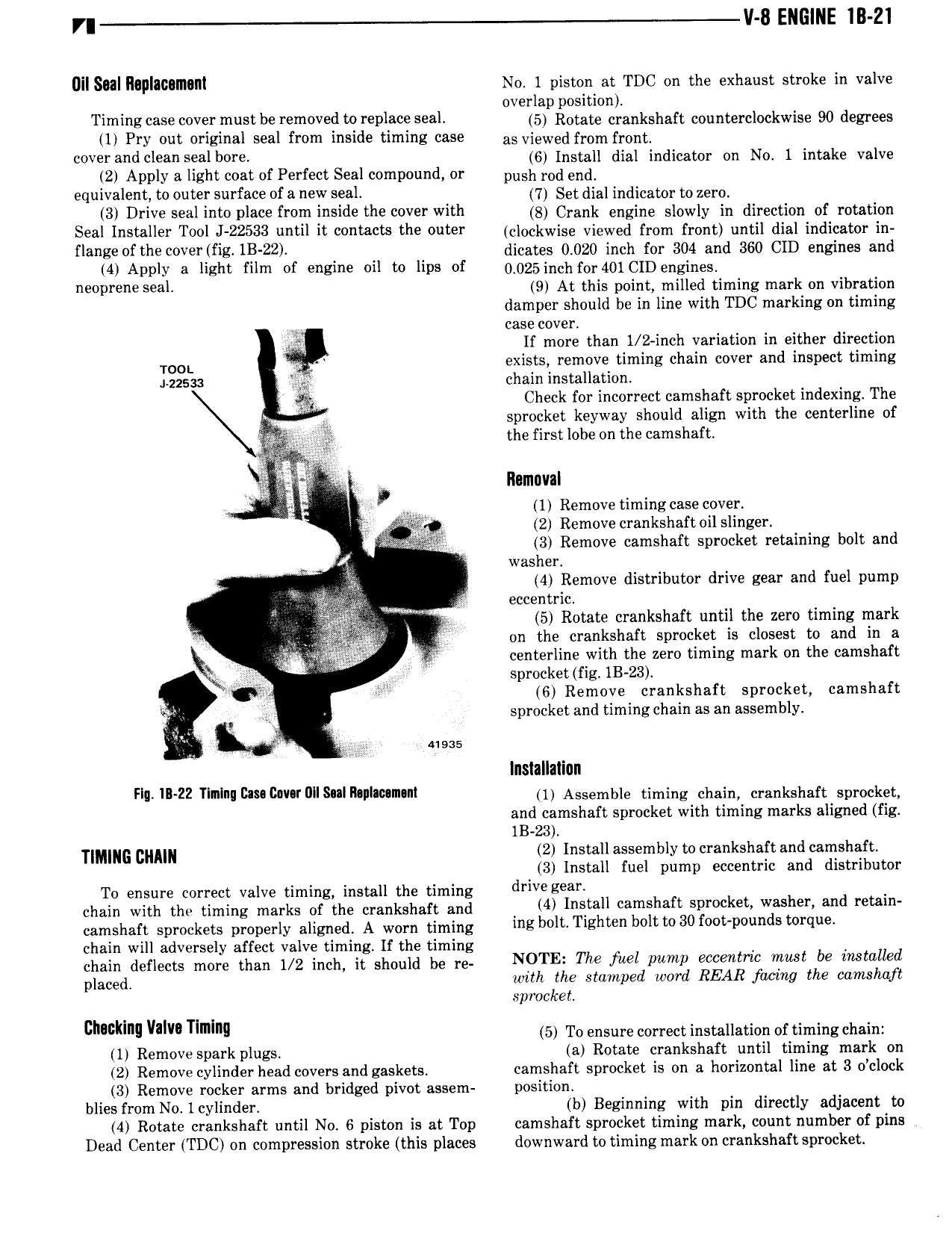
r V 8 ENGINE IB Z1 Dilslll ll0 IllI2lI llIIl No I piston at TDC on the exhaust stroke in valve overlap position Timing case V Y mlm be Y m0Vl d 0 l Dl Seal 5 Rotate crankshaft counterclockwise 90 degrees 1 Pry out original seal from inside timing case as viewed from front mverandclean aib l 6 Install dial indicator on No 1 intake valve 2 Apply a light coat of Perfect Seal compound or push rod end equivalent to outer surface of a new seal 7 get dia indieaton to Zend 3 Drive seal into place from inside the cover with 3 Crank engine eiowiy in direction of rotation Seal Installer Tool J 22533 until it contacts the outer eiookwise viewed fi om front untii dial indicator in flange of the cover fig 1B 22 dicates 0 020 inch for 304 and 360 CID engines and 4 Apply a light film vf engine vil to lips of 0 025inch for 401 CID engines 0l 9ll Wal 9 At this point milled timing mark on vibration damper should be in line with TDC marking on timing case cover ii If more than I 2 inch variation in either direction TOOL exists remove timing chain cover and inspect timing 225 4 chain installation ig Check for incorrect camshaft sprocket indexing The 4 sprocket keyway should align with the centerline of the first lobe on the camshaft Ilamnval i 1 Remove timing case cover t 2 Remove crankshaft oil slinger Af 3 Remove camshaft sprocket retaining bolt and washer Y 4 Remove distributor drive gear and fuel pump eccentric 5 Rotate crankshaft until the zero timing mark Q f on the crankshaft sprocket is closest to and in a i Y A T centerline with the zero timing mark on the camshaft sprocket fig 1B 23 6 Remove crankshaft sprocket camshaft r sprocket and timing chain as an assembly g usas Installation Fl 1 22 Tlmlriu v r llS lll nl m nt 1 Assemble timing chain mhiahart Sprocket and camshaft sprocket with timing marks aligned fig 1B 23 M culm 2 Install assembly to crankshaft and camshaft 3 Install fuel pump eccentric and distributor To ensure correct valve timing install the timing d lV E a chain with the timing marks of the crankshaft and V 4 Install camshaft sprocket washer and retain camshaft Sprockets properly aligned A wm timing me l lt T sl t lwltte 30f p d i 4 chain will adversely affect valve timing If the timing chain denote more thah 1 2 iheh at should be he N0 l E The fw www ecvemcv mw be Mwlulled placed with the stamped word REAR facing the camshaft sprocket cnwklng VII Tim 5 To ensure correct installation of timing chain 1 Remove spark plugs a Rotate crankshaft until timing mark on 2 Remove cylinder head covers and gaskets camshaft sprocket is on a horizontal line at 3 o clock 3 Remove rocker arms and bridged pivot assem position blies from No lcylinder b Beginning with pin directly adjacent to 4 Rotate crankshaft until No 6 piston is at Top camshaft sprocket timing mark count number of pins Dead Center TDC on compression stroke this places downward to timing mark on crankshaft sprocket

 Next
Next