Ford Parts Wiki | GM Parts Wiki
Home | Search | Browse | Marketplace | Messages | FAQ | Guest
|
Technical Service Manual January 1975 |
|
Prev

 Next
Next
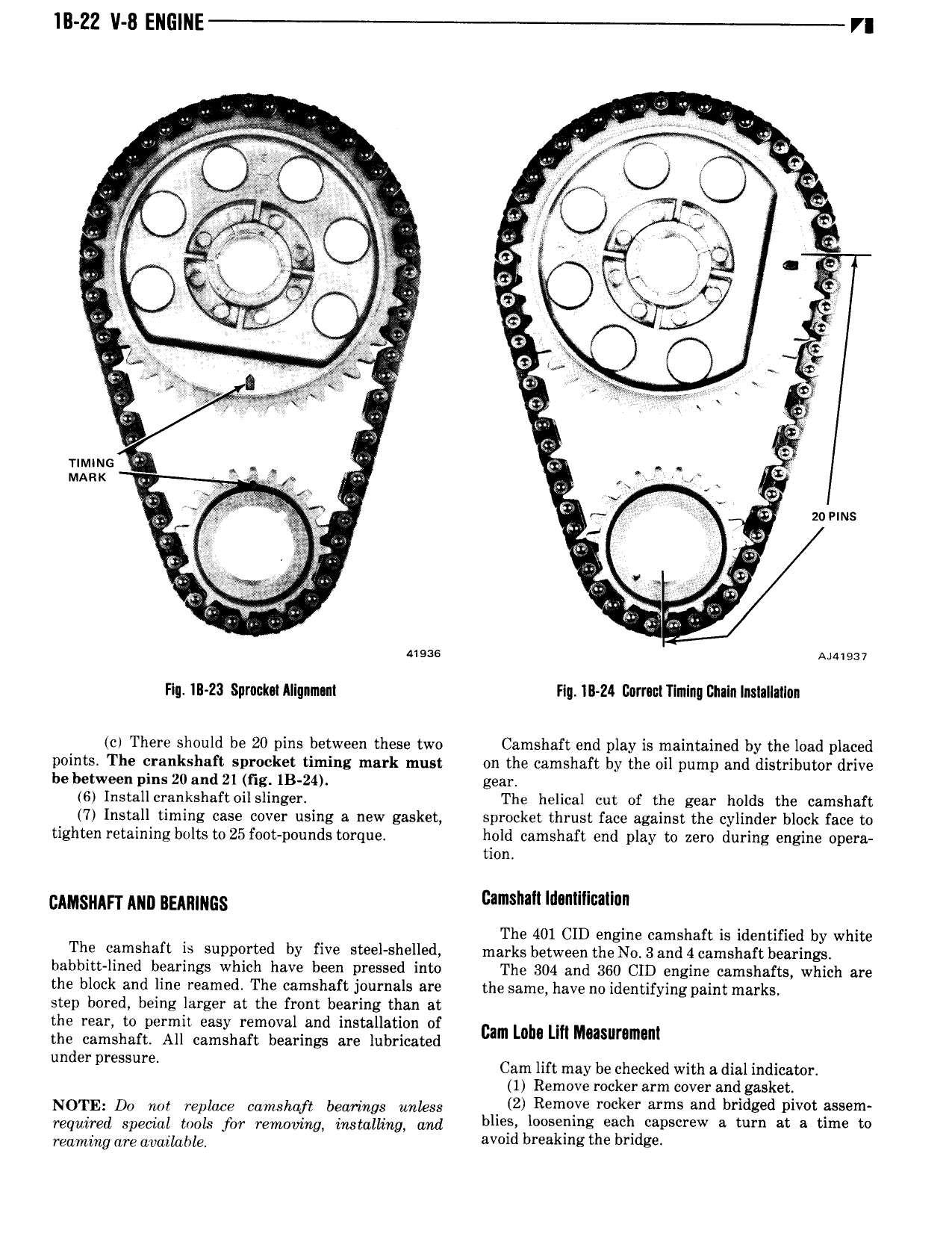
lB ZZ V 8 ENGlNE VI w U I O V li I ll V kj li Q J 5 O 4 AU to c I V t I Q s r t Cf 7 e An t x 0 x Q G I Q F x e r J i Eg x Timms U l QD i MARK x Qi 45 w l E zoems s 4 qi awe ga T P Mm mw Flu 1B 23 Sprumt Allgnmnnt F q 1I1 Zl 00mctT mlng I21I lnInsIa It1 0n cl There should be 20 pins between these two Camshaft end play is maintained by the load placed points The crankshaft sprocket timing mark must on the camshaft by the oil pump and distributor drive be between pins 20 and 21 fig 1B 24 gear 6 Installcrankshaftoilslinger The helical cut of the gear holds the camshaft 7 Install timing case cover using a new gasket sprocket thrust face against the cylinder block face to tighten retaining bolts to 25 foot pounds torque hold camshaft end play to zero during engine opera tion cmsnm Mm BEARINGS Camshaft Idantlllcallan The 401 CID engine camshaft is identified by white The camshaft is supported by five steel shelled marks between theNo 3and4camshaft bearings babbitt lined bearings which have been pressed into The 304 and 360 CID engine camshafts which are the block and line reamed The camshaft journals are the same have no identifying paint marks step bored being larger at the front bearing than at the rear to permit easy removal and installation of the camshaft All camshaft bearings are lubricated cam Loh lm Musummam under pressure Cam lift may be checked with a dial indicator 1 Remove rocker arm cover and gasket NOTE Do not replace camshaft bearings unless Zi Remvve rocker arms and bridged pivot assem requimd Special tools fw mymvmgy immlli Lg and blies loosening each capscrew a turn at a time to Teaming me amimhla avoid breaking the bridge

 Next
Next