Ford Parts Wiki | GM Parts Wiki
Home | Search | Browse
|
Technical Service Manual January 1975 |
|
Prev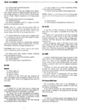
 Next
Next
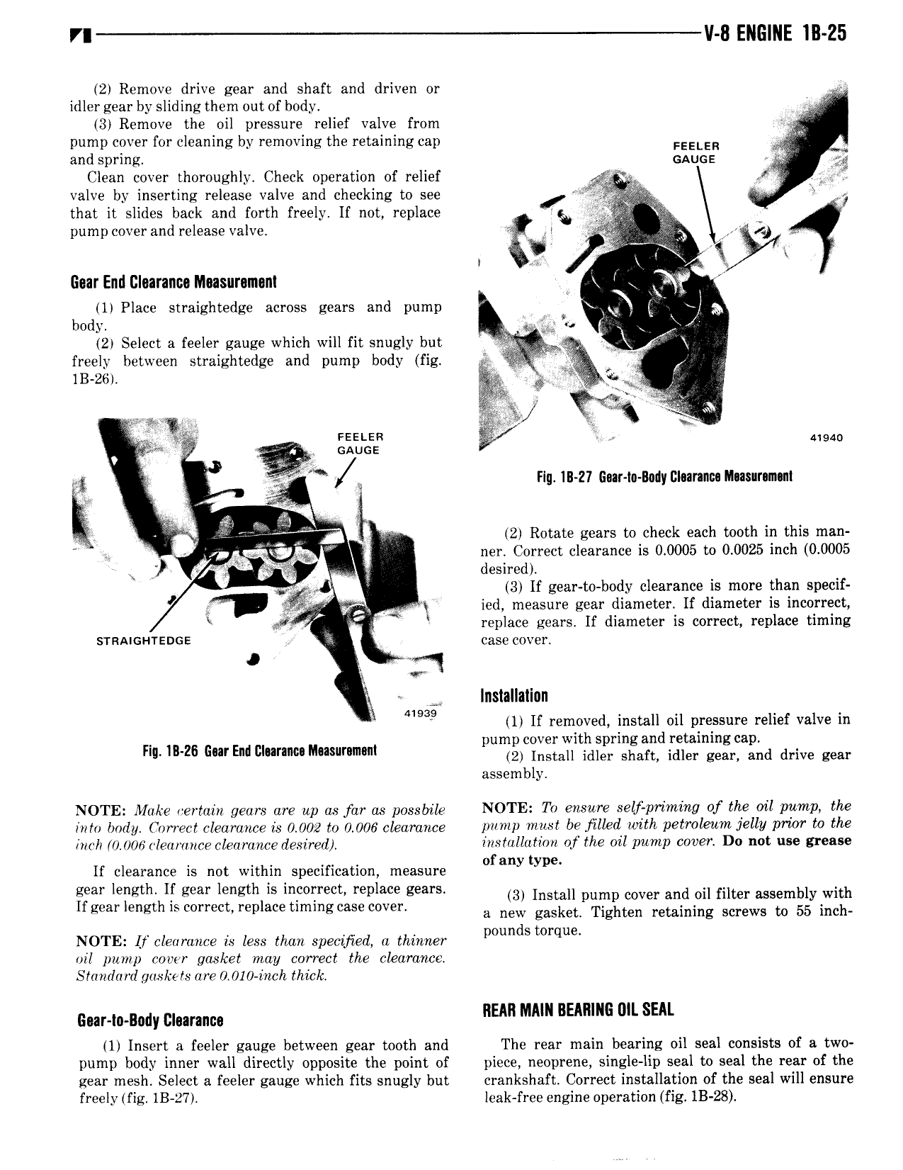
r V 8 ENGINE IB 25 2 Remove drive gear and shaft and driven or idler gear by sliding them out of body y 3 Remove the oil pressure relief valve from pump cover for cleaning by removing the retaining cap FEELER V and spring GAUGE Clean cover thoroughly Check operation of relief fi valve by inserting release valve and checking to see 7 that it slides back and forth freely lf not replace Y pump cover and release valve rg V I l t Gear End Illoaranca Nlaasurumant Q l 1 Place straightedge across gears and pump i i i 5 body Q 2r Select a feeler gauge which will fit snugly but I S4 freely between straightedge and pump body fig X f 1B 26a g 3 V 5 2 wg 3 ag Fasten V alarm l GAUGE V L l FIu IIl 27 Gaar to Body Clnranuu Musnrnmnnl i rive 2 Rotate gears tokcheck each tooth in this man p ka ner Correct clearance 1s 0 0005 to 0 0025 inch 0 0005 l desired V V 3 If gear to body clearance is more than specif V VS ied measure gear diameter If diameter is incorrect l V replace gears If diameter is correct replace timing svnnncnrsoos case cover I Q X A lnstallallnn 41939 1 If removed install oil pressure relief valve in pump cover with spring and retaining cap F II 26 iwE l l 42 intent idler shan idler gear and time gw assembly NOTE Make certain gears are up as far as posslrlle NOTE1 Tv WLSWF S lf Pt imi Q of UQ Ol WWP the mm lazy Umm clearance is 0 002 l0 0 006 clearance p 0u mst be Hllvrl with petroleum Jelly www the inch 0 006 lem 0m clearance desired MSM Iufwn of the ml Pump COWT4 D0 Mt IM 8T S f t If clearance is not within specification measure 0 any ype gear lellglll ll gear length ls lnlolrem replace geam 3 Install pump cover and oil filter assembly with Ifgear length is correct replace timingcase cover a new gasket Tighten retaining Screws to 55 inch d NOTE Lf clearance is less than speclferl a thlnner lmun Smrque nil pump cover gasket may correct the clearance Standard gaskets are 0 010 inch thick I EAL Gw m B dy ummm IIEAR MAIN BEARING 0 LS tl Insert a feeler gauge between gear tooth and The rear main bearing oil seal consists of a two pump body inner wall directly opposite the point of piece neoprene single lip seal to seal the rear of the gear mesh Select a feeler gauge which fits snugly but crankshaft Correct installation of the seal will ensure freely fig 1B 27 leak free engine operation fig lB 28