Ford Parts Wiki | GM Parts Wiki
Home | Search | Browse
|
Technical Service Manual January 1975 |
|
Prev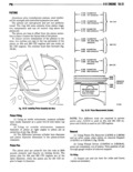
 Next
Next
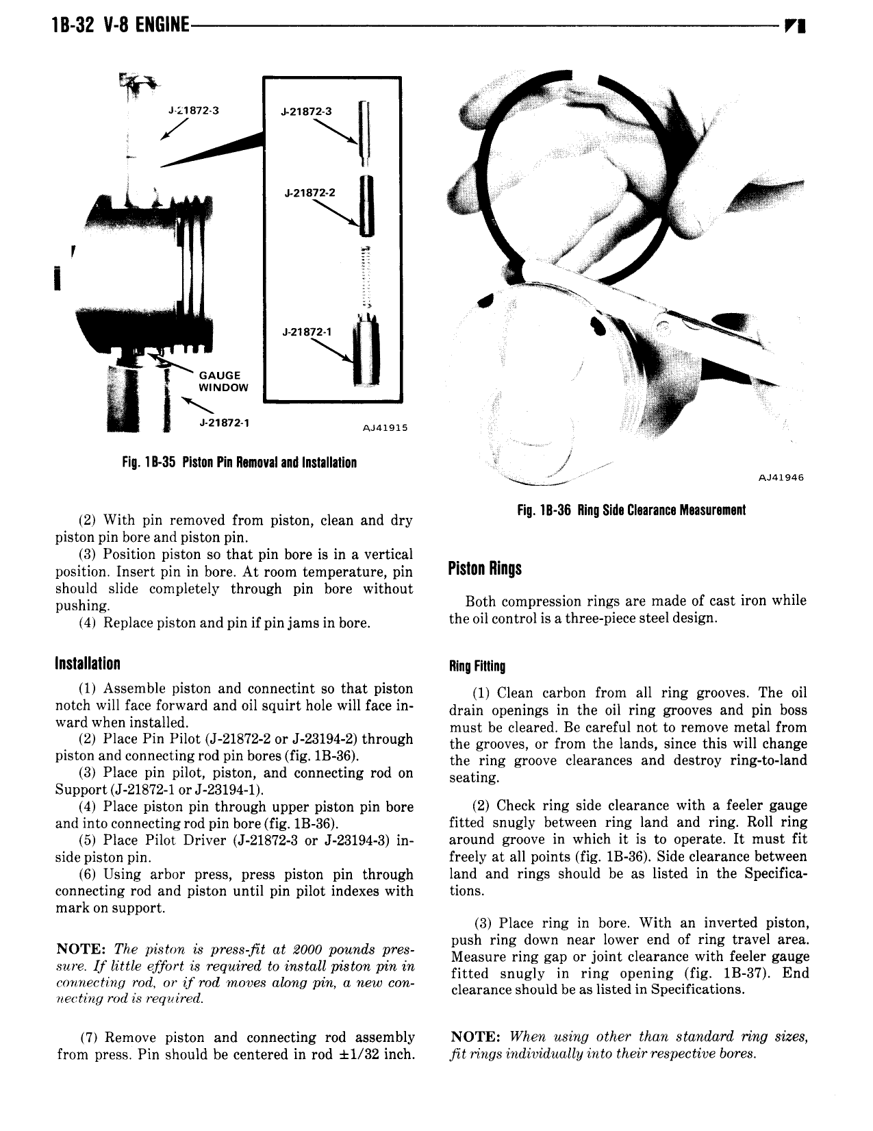
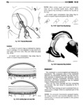
in 32 v 8 ENGlNE n r i iusvza izisna r V Z iz1a12 2 K I i 2 e ex z1s1z i it or if l w e y X 2 2 Amore FI IB 35 Plstnn Pin Ilunml and Installatlan Y V Ammo F l Il nl EI M ni 2 With pm removed from piston clean and dry lg B 36 mg sl l umm uw piston pin bore and piston pin 3 Position piston so that pin bore is in a vertical position Insert pin in bore At room temperature pin Plslml mills should slide completely through pin bore without pushing Both compression rings are made of cast iron while 4 Replace piston and nin if nin jams in bona the oil control is a three piece steel design lnatallatlun lllnu rmmq U Assemble vi Md e ee i ee thee vieien 11 Clean carbon from all ring grooves The oil notch will face forward and o1l squirt hole will face in drain Openings in the Oil ring gmnvaa and nin boss Weed when l tf H l must be cleared Be careful not to remove metal from 2 Place Pm t J 2 872 2 L23194 2 through the grooves or from the lands since this will change mswnandmnnecunerod1 mb res f s 113 36 me ring groove clearances and destroy ring to land 3 Place pin pilot piston and connecting rod on seating Support J 21872 1 or J 23194 1 4 Place piston pin through upper piston pin bore 2 Check ring side clearance with a feeler gauge and into connectingrod pin bore fig IB 36 fitted snugly between ring land and ring Roll ring 5 Place Pilot Driver J 21872 3 or J 23194 3 in around groove in which it is to operate It must fit side piston pin freely at all points fig 1B 36 Side clearance between 6 Using arbor press press piston pin through land and rings should be as listed in the Specifica connecting rod and piston until pin pilot indexes with tions mark Ol S lpp0 t 3 Place ring in bore With an inverted piston push ring down near lower end of ring travel area NOTE The mmm is mes qt at 2000 minds Me Measure ring gap or joint clearance with feeler gauge sure If little effort is required to install piston pin in fitted snugl in ring Opening fig 1B 37 End P iieme me V me mee me eee e eee eee clearance soothe be as listed re Specifications rieamig rod is required 7r Remove piston and connecting rod assembly NOTE When using other than standard ring sizes from press Pin should be centered in rod 11 32 inch jitiings individually into their respective bores