Ford Parts Wiki | GM Parts Wiki
Home | Search | Browse
|
Technical Service Manual January 1975 |
|
Prev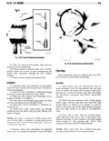
 Next
Next
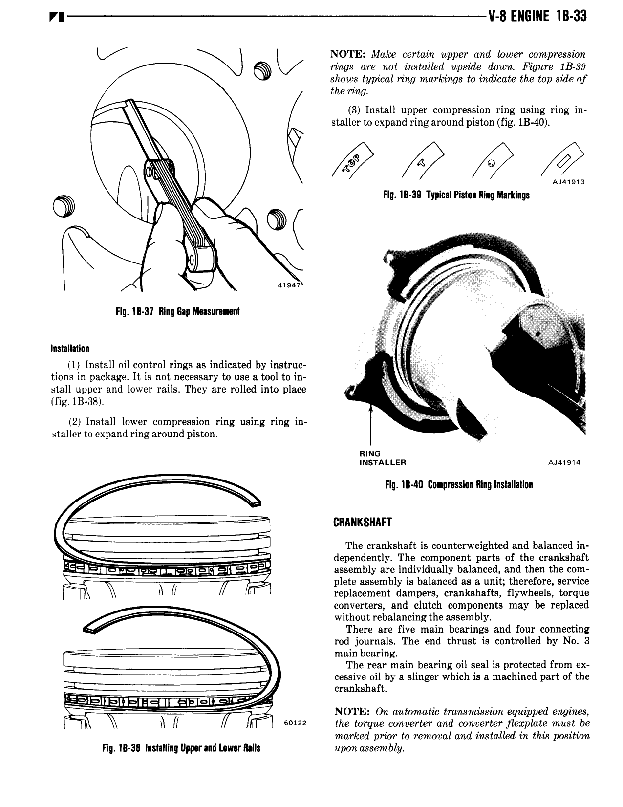
r v 8 ENGINE IB 33 KX NOTE Make certain upper and lower compression Hugs are not installed upside down Figure IB 39 shows typibal ring markings to indicate the top side of the ring A 3 Install upper compression ring using ring in staller to expand ring around piston fig 1B 40 A s A Q A w WA Fly IB 39 Typtcal Piston Nlnq Ihrklngs I M Q 41s4v Hq 1It 31 Ring Gap Musunmunl E A g g V V in tt Installatlon x 1 Install oil control rings as indicated by instruc tions in package It is not necessary to use a tool to in Y p stall upper and lower rails They are rolled into place 4 fig 1B 38 E 2 Install lower compression ring using ring in staller to expand ring around piston smc tusnttsn mma X Fig t 40 Compmslnn Ntnq Installattnn The crankshaft is counterweighted and balanced in dependently The component parts of the crankshaft EEIEIiEa 4sya g 1 dEI lK aF assembly are individually balanced and then the com plete assembly is balanced as a unit therefore service I h li replacement dampers crankshafts flywheels torque converters and clutch components may be replaced VE 7 V V without rebalancing the assembly There are five main bearings and four connecting rod journals The end thrust is controlled by No 3 main bearing The rear main bearing oil seal is protected from ex cessive oil by a slinger which is a machined part of the crankshaft E lElE IIE EE lK I3ElEl I 2l NOTE On automatic transmissicm equipped engines h 5 122 the torque converter and converter flexplate must be marked prior to removal and instalkd in this position Ft II 3I Instatllng Ilpp r nd Lawr Natl upon assembly