Ford Parts Wiki | GM Parts Wiki
Home | Search | Browse | Marketplace | Messages | FAQ | Guest
|
Technical Service Manual January 1975 |
|
Prev
 Next
Next
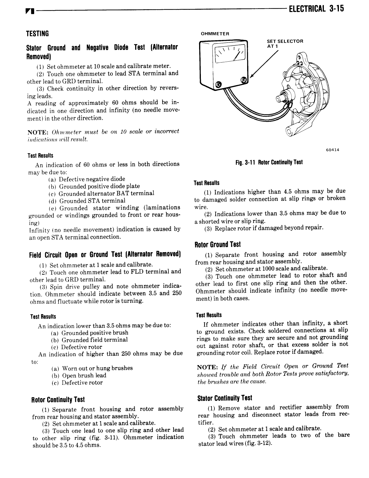
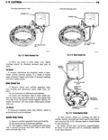
VI ELECTRICAL 3 15 TESTING oruvlmersn Slater Ground and Negative Diode Test Alternator i iT sELE T R Removed Q 1l Set ohmmeter at 10 scale and calibrate meter 2 Touch one ohmmeter to lead STA terminal and QM other lead to GRD terminal I0 I r 3 Check continuity in other direction by revers n x ing leads Vw v A reading of approximately 60 ohms should be in lg L dicated in one direction and infinity no needle move I ment in the other direction NOTE Ohrrmeter must be rm 10 scale or incorrect Q imlicurirms will result Test Results 6 An indication of 60 ohms or less in both directions Flu 3 II Mitt COIi nllI yTe may he due to a Defective negative diode b Grounded positive diode plate Tm msum cl Grounded alternator BAT terminal 1 Indications higher than 4 5 ohms may be due dt Grounded STA terminal to damaged solder connection at slip rings or broken el Grounded stator winding laminations wire grounded or windings grounded to front or rear hous 2 Indications lower than 3 5 ohms may be due to i t a shorted wire or slip ring Infinity no needle movement indication is caused by 3 Replace rotor if damaged beyond repair an open STA terminal connection Rotor Ground Test Field Circuit Upon or Ground Test Alternator Removed lll Separate lnsns nenslng and ness assembly 1 Set ohmmeter at 1 scale and calibrate from Yea housing and stator mblY 2 Touch one ohmmeter lead to FLD terminal and 2l Sewhmmeter a 1000 l mi l b Oslneln lead se GRD l ennnlnal 3 Touch one ohmmeter lead to rotor shaft and gl Spin dnlve pulley and note ohmmeter lndlaa other lead to first one slip ring and then the other llen Ollmmeten Should lndlcase between 3 5 and 250 Ohmmeter should indicate infinity no needle move ohms and fluctuate while rotor is turning ment in bvfh ca5 Test Results Test mulls An indication lower than 3 5 ohms may be due to If ohmmeter indicates other than infinity a short a Grounded positive brush to ground exists Check soldered connections at slip br Grounded field terminal rings to make sure they are secure and not grounding cl Defective rotor out against rotor shaft or that excess solder is not An indication of higher than 250 ohms may be due grounding rotor coil Replace rotor if damaged to a Worn outor hungbrushes NOTE If the Field Circuit Open or Ground Test b Open brush lead showed trouble and both Rotor Tests prove satisfactory c Defective rotor the brushes are the cause Rotor Continuity Test Slater Continuity Test 1 Separate front housing and rotor assembly 1 Remove stator and rectifier assembly from from rear housing and stator assembly rear housing and disconnect stator leads from rec 2 Set ohmmeter at 1 scale and calibrate tifier 3 Touch one lead to one slip ring and other lead 2 Set ohmmeter at 1 scale and calibrate to other slip ring fig 3 11 Ohmmeter indication 3 Touch ohmmeter leads to two of the bare should be 3 5 to 4 5 ohms stator lead wires fig 3 12