Ford Parts Wiki | GM Parts Wiki
Home | Search | Browse | Marketplace | Messages | FAQ | Guest
|
Technical Service Manual January 1975 |
|
Prev
 Next
Next
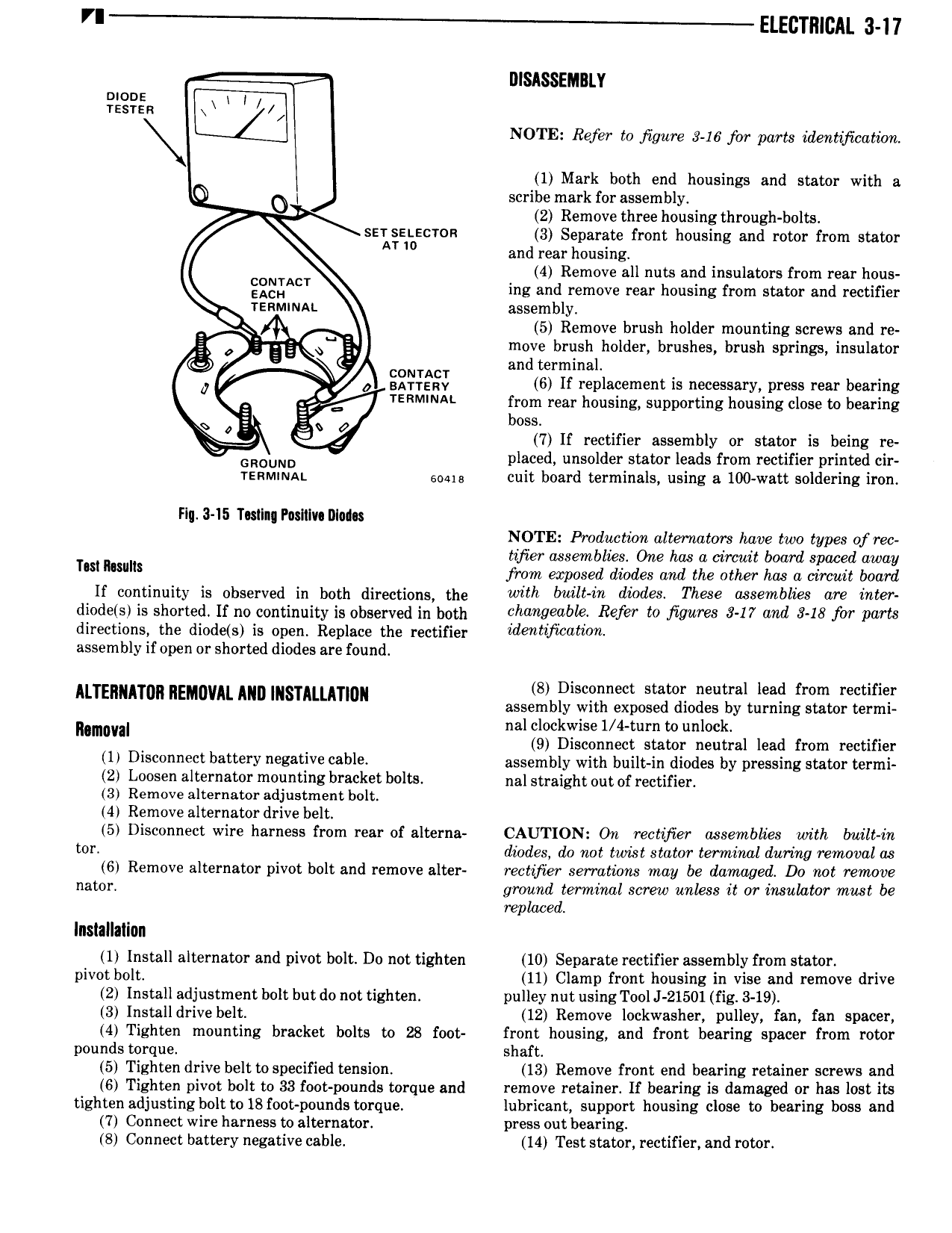
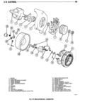
VI ELECTRICAL 3 17 DISASSEMBLY Tssrsk moo NOTE Refer to jigure 3 16 for parts identfcaticrri 1 Mark both end housings and stator with a O O I scribe mark for assembly 2 Remove three housing through bolts ser snscron 3 Separate front housing and rotor from stator AT w and rear housing 4 Remove all nuts and insulators from rear hous EEQSACT ing and remove rear housing from stator and rectifier TERMMAL assembly 5 Remove brush holder mounting screws and re g Q QE move brush holder brushes brush springs insulator 4 A G and terminal 0 S2 bi gd 6 lf replacement is necessary press rear bearing TERM NA from rear housing supporting housing close to bearing E boss R 7 7 If rectifier assembly or stator is being re GROUND placed unsolder stator leads from rectifier printed cir renmnuat time cuit board terminals using a 100 watt soldering iron Fin 3 15 Tostlng P IlIv l I0l NOTE Production alternators luwe two types of rec tifier assemblies One has a circuit board spaced away Tm mulls from exposed diodes and the other has a circuit board ii continuity is nbseiveii in both directions the wiiii iiiii iri diodes These assemblies ars iiiier diode s is shorted If no continuity is observed in both Qhandeftbl Refw 0 Ji9W 3 17 and 348 fw Pans directions the diode s is open Replace the rectifier idmhfwahon assembly if open or shorted diodes are found S Disconnect stator neutral lead from rectifier M TE AT0 REMIWAL Mm INSTMLATIDN assembly with exposed diodes by turning stator termi naman nal clockwise 1 4 turn to unlock 9 Disconnect stator neutral lead from rectifier 1 Disconnect battery negative cable assembly with built in diodes by pressing stator termi 2 Loosen alternator mounting bracket bolts nal straight out of rectifier 3 Remove alternator adjustment bolt 4 Remove alternator drive belt 5 Disconnect wire harness from rear of alterna CAUTION On rectifier assemblies with built in tor diodes do not twist stator terminal during removal as 6 Remove alternator pivot bolt and remove alter rectifier serrations may be damaged Do not remove nator ground terminal screw unless it or insahztor must be replaced Installation 1 Install alternator and pivot bolt Du not tighten 10 Seperate rectifier assembly from stator pivot bolt 11 Clamp front housing in vise and remove drive 2 lnstall adjustment bolt but do not tighten pulley nut using Tool J 21501 fig 3 19 3 Install drive belt 12 Remove lockwasher pulley fan fan spacer 4 Tighten mounting bracket bolts to 28 foot front housing and front bearing spacer from rotor pounds torque shaft 5 Tighten drive belt tospecified tension 13 Remove front end bearing retainer screws and 6 Tighten pivot bolt to 33 foot pounds torque and remove retainer lf bearing is damaged or has lost its tighten adjusting bolt to 18 foot pounds torque lubricant support housing close to bearing boss and 7 Connect wire harness to alternator press out bearing 8 Connect battery negative cable 14 Test stator rectifier and rotor