Ford Parts Wiki | GM Parts Wiki
Home | Search | Browse | Marketplace | Messages | FAQ | Guest
|
Technical Service Manual January 1975 |
|
Prev
 Next
Next
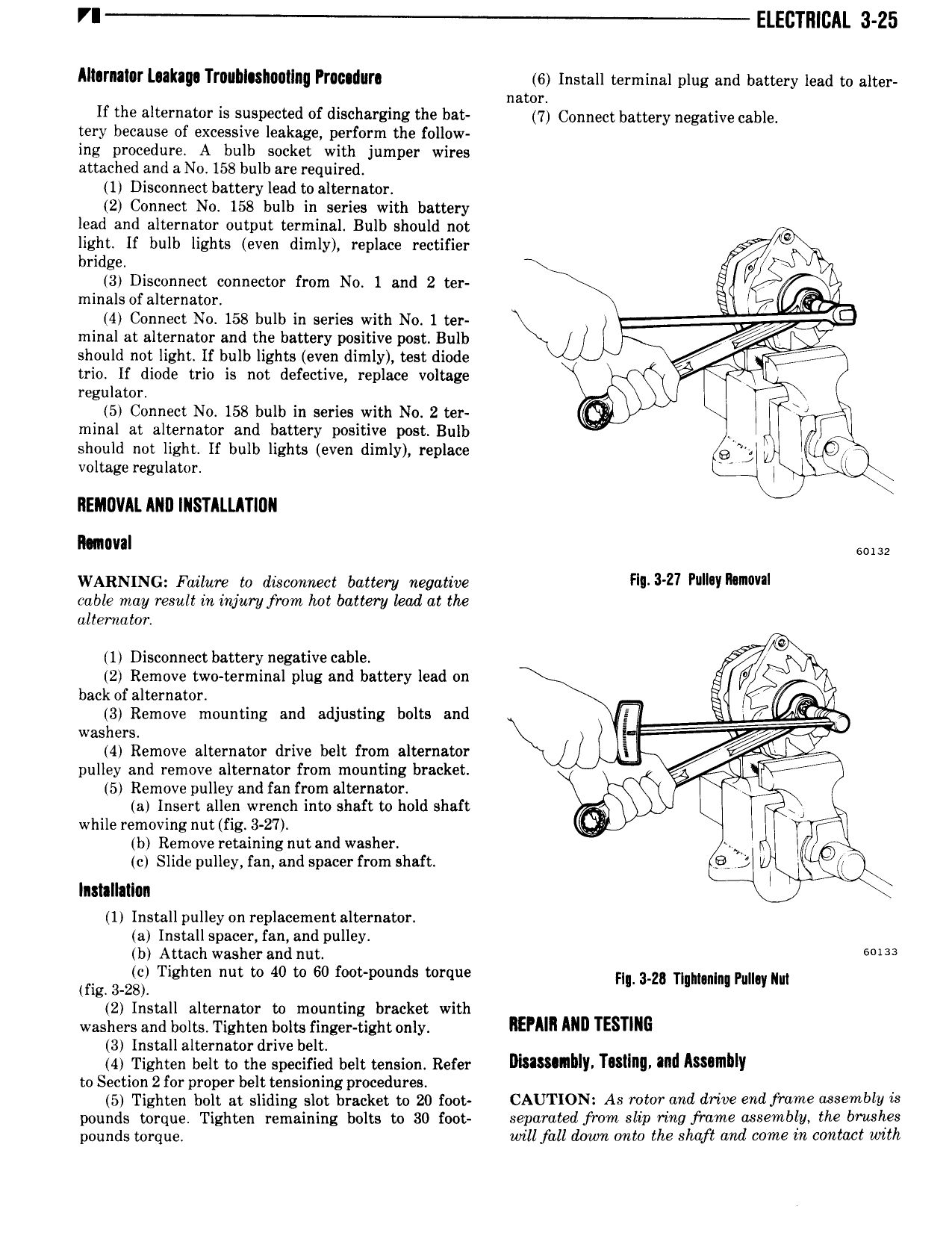
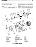
VI Eircrmcni 3 25 Alhrnalor L akag Trnubluhnatlng Procedure 6 Install terminal plug and battery lead to nim nator If the alternator is suspected of discharging the bat 7 Connect battery negative cable tery because of excessive leakage perform the follow ing procedure A bulb socket with jumper wires attached and a No 158 bulb are required 1 Disconnect battery lead to alternator 2 Connect No 158 bulb in series with battery lead and alternator output terminal Bulb should not light If bulb lights even dimly replace rectifier 0 bridge W y 3 Disconnect connector from No 1 and 2 ter l minals of alternator 4 Connect No 158 bulb in series with No 1 ter minal at alternator and the battery positive post Bulb 4QST should not light if bulb lights even dimly test diode trio if diode trio is not defective replace voltage l regulator 5 Connect No 158 bulb in series with No 2 ter minal at alternator and battery positive post Bulb should not light if bulb lights even dimly replace Qi voltage regulator E REMOVAL ANI IIISTALLATIIIII l mm WARNING Failure to dtsczmnect battery negative H 3 z7 FWIW Mnvvrl cable may result in injury from hot battery lead at the alternator r 0 1 Disconnect battery negative cable li x 2 Remove two terminaI plug and battery lead on 5 YL back of alternator iq n 3 Remove mounting and adjusting bolts and Y E A m washers 4 Remove alternator drive belt from alternator e pulley and remove alternator from mounting bracket 5 Remove pulley and fan from alternator a Insert allen wrench into shaft to hold shaft while removing nut fig 3 27 b Remove retaining nut and washer h c Slide pulley fan and spacer from shaft Q J k Inslallallan l 1 Install pulley on replacement alternator a Install spacer fan and pulley b Attach washer and nut SMH mg 3 zg Tighten nut to 40 to 60 foot pounds torque HL 34 Hamm Pu mn 2 Install alternator to mounting bracket with washers and bolts Tighten bolts finger tight only IEYMI mn TESTING 3 Install alternator drive belt 4 Tighten belt to the specified belt tension Refer Dhasunhly Tutlng and Assamhly to Section 2 for proper belt tensioning procedures 5 Tighten bolt at sliding slot bracket to 20 f0ot CAUTION As rotor and drive end frame assembly is pounds torque Tighten remaining bolts to 30 foot separated from slip ring frame assembly the brushes pounds torque will fall down onto the shaft ami come in contact with