Ford Parts Wiki | GM Parts Wiki
Home | Search | Browse | Marketplace | Messages | FAQ | Guest
|
Technical Service Manual January 1975 |
|
Prev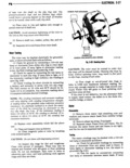
 Next
Next
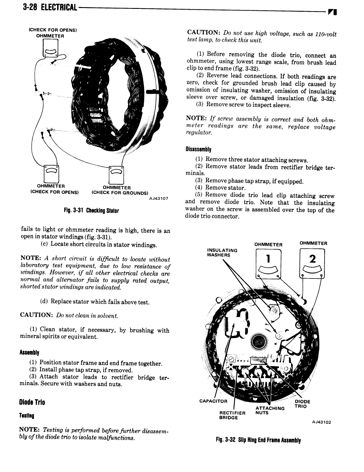
3 28 ElECTI lCAL r cn neck ron ovens CAUTION Do not use high voltage such as 110 volt MMElER I test lamp to check this unit ll 1 Before removing the diode trio connect an r ohmmeter using lowest range scale from brush lead L eliptoend frame fig 3 32 Il J 2 Reverse lead connections If both readings are K ptr zero check for grounded brush lead clip caused by y wig i omission of insulating washer omission of insulating L me J Qu sleeve over screw or damaged insulation fig 3 32 r i Q 3 Remove screw to inspect sleeve l gi l it V NOTE U screw assembly is correct and both ohm Q v meter readings are the same replace voltage l i rewilator rt T nlsammhly 1 Remove three stator attaching screws 2 Remove stator leads from rectifier bridge ter minals W W 3 Remove phase tap strap if equipped oummsren oummersn 4 Remove Stamf lcnzcx Fon ovens icnecx son cnouunsi 5 Remove diode trio lead clip attaching screw A 1 7 and remove diode trio Note that the insulating ml am mmm war sil e ri r 2 w is assembled over the top of the fails to light or ohmmeter reading is high there is an open in stator windings fig 3 31 c Locate short circuits in stator windings INSULAYING MMHER OHMMETER wasnsns NOTE A short circuit is difficult to locate without laboratory test equipment due to low resistance of windings However if all other electrical checks are normal and alternator fails to supply rated output shorted statorwindings areindizated g d Replace stator which fails above test g r ax 7 CAUTION Donot chan in solvent V ii l Q Y 1 Clean stator if necessary by brushing with lh I l N mineral spirits or equivalent Apt ut Y 4 x v mnhly rv li r H if 1 Position stator frame andend frame together iiijl ml O It O 2 Install phase tap strap if removed Q 4 3 Attach stator leads to rectifier bridge ter ii M rninals Secure with washers and nuts 5 gf ix X j i cancnron X 0 E Dllldl Tl lII ag cunnc TR nec an a ru snags E Analog NOTE Testing is performed be one further disassem bly of the diode trio to isolate malfunctions F 3 32 Slip lllnq Enl Fran Awtlbly