Ford Parts Wiki | GM Parts Wiki
Home | Search | Browse | Marketplace | Messages | FAQ | Guest
|
Technical Service Manual January 1975 |
|
Prev
 Next
Next
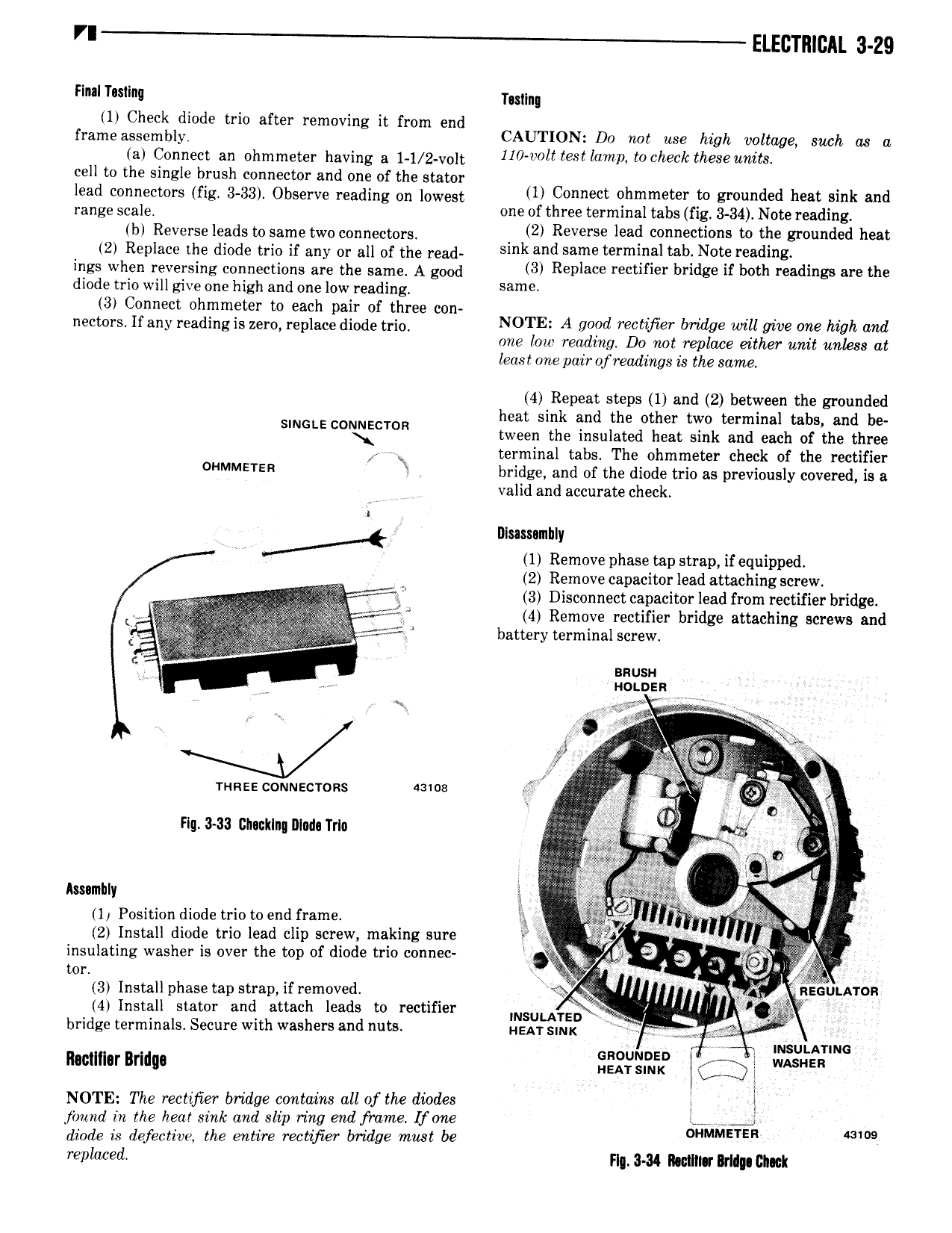
rr ELECTRICAL 3 29 Flnal Tustlnq ll Check diode trio after removing it from end frame nssemmy CAUTION D0 not use high voltage such as a ia Connect an Dhmmewr having 3 1 1 2 v01t 110 volt tectlamp tocheck theseunits cell to the single brush connector and one of the stator lead connectors fig 3 33 Observe reading on lowest lil Connect qiimmewr to zwvnded hear sink and range sea e one of three terminal tabs fig 3 34 Note reading bl Reverse leads to same two connectora 4 2 Reverse lead connections to the grounded heat 2 Replace the diode trio if any or all of the read sink and Same terminal rail New r d z ings when reversing connections are the same A good 3 R Piac rectifier bridge ir both i a iii iB are the diode trio will give one high and one low reading Samir 3 Connect ohmmeter to each pair of three con g necwrs ir any reading is zero repiace diode md N0TE A wd remfier badge MU we vw Mah and one lou reading D0 not replace either unit unless at least one pair of readings is the same 4 Repeat steps 1 and 2 between the grounded heat sink and the other two terminal tabs and be SINGLE COLQECTOR tween the insulated heat sink and each of the three terminal tabs The ohmmeter check of the rectifier onmmarzn rl bridge and of the diode trio as previously covered is a valid and accurate check I Y V Dlussnmhly i 1 Remove phase tap strap if equipped 2 Remove capacitor lead attaching screw E 3 Disconnect capacitor lead from rectifier bridge L V at I j g j F 4 Remove rectifier bridge attaching screws and i g fi irf s f battery terminal screw anusu 1 V uotnsn ir 9 in Kys Oy 1 fg i 2 n runs couwecrons dame ef j yl r l fl 5 Q Ig 3 33 Gnuuklng Illudn Trlo I mq s 1 r m r r o 34 i ngggvi r v Assamhly xi Ai 1 Position diode trio to end frame ix I in 2 Install diode trio lead clip screw making sure r i l insulating washer is over the top of diode trio connec 4 It mn J 3r Installphase tap strap ifremoved gi nscunrron 4 Install stator and attach leads to rectifier INSULAYED bridge terminals Secure with washers and nuts HEAT SINK 4 U msun A1 ma Roctlllor Brldua 2 f l j 7 WASHER NOTE The rectifier bridge contains all of the dundee I jbnnd in the hear sink and slip ring end frame fone an diode is defective the entire rectifer bridge must be MLMMETER l r nkwed rn H4 nwimar may CIM